Landscape intelligence for Revit

LandForm.
Shape the Ground.
Define the Future.

A focused toolkit—and a growing learning library—for landscape architects building better terrain, planting, analysis, and documentation workflows in Revit.

Built forLandscape architectureWorks withAutodesk Revit 2024–2027

Less workaround.
More landscape.

LandForm brings the repetitive, disconnected parts of landscape production into one considered toolkit—so your model stays useful from first terrain move to final issue.

01

Shape terrain

Create mounds, grading studies, overlays, and precise edge relationships directly in Revit.

02

Design planting

Build repeatable planting mixes, distribute families, annotate palettes, and keep quantities coordinated.

03

Document clearly

Generate legends, sheets, exports, schedules, and color studies without breaking your model rhythm.

04

Connect your data

Move cleanly between Revit, CAD, Excel, LandXML, and the information your project already uses.

Watch the workflow

See the tool.
Understand the move.

Short, focused studies showing how LandForm turns design intent into coordinated Revit work.

Subscribe on YouTube
Always currentThe player follows the latest LandForm uploads.

Return whenever you need a new technique, a faster workflow, or a fresh way to test a landscape idea.

From contour
to construction.

Purpose-built commands that respect how landscape projects actually develop.

Terrain

  • +Grading Assistant
  • +Mounds
  • +Match Edge
  • +Filler

Planting

  • +Plant Mix
  • +Surface Mix
  • +Connectors
  • +Schedules

Analysis

  • +Shade Coverage
  • +Color Splash
  • +Surface Legends
  • +Filter Legends

Delivery

  • +Document Export
  • +Sheet Series
  • +LandXML
  • +Model CleanUp

Ideas worth
returning to.

Practical notes behind the videos—written for landscape teams who want the principle, not only the button.

01Pattern systems

Design variation without drawing every variation.

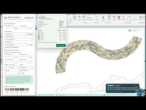
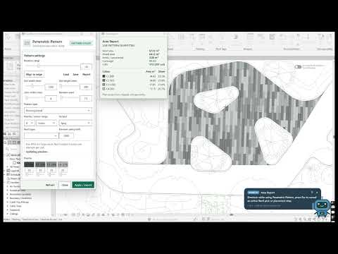
Parametric paving is most useful when the rule remains visible. Start with a repeatable unit, expose the variables that matter, then let density and dissolve respond to the site instead of redrawing the field by hand.

Watch the study
02Terrain practice

Treat topography as design data, not a finished backdrop.

A terrain study should stay easy to question. Small, reversible sculpting moves help teams test spatial character early while preserving the coordinated surface needed for later documentation.

Watch the study
03Delivery workflow

Export only what the next person can actually use.

Clean delivery begins before export. A layer-aware workflow reduces cleanup, protects graphic intent, and gives consultants a file that carries the project structure forward instead of flattening it away.

Watch the study
New studiesAs the toolkit evolves
Built aroundReal landscape workflows
Open the full video library

Every ribbon command

Know what to use.
Know what comes next.

This practical guide follows the current LandForm tooltips. Open any tool to see what it does and the normal sequence to follow in Revit.

LF / GUIDECURRENT
69 DOCUMENTED TOOLSPurpose • Sequence • Result
Panels11
Documented tools69

Use the panel index to jump to a workflow. Expand a tool for its step-by-step guideline.

01

Interop

8 tools

Interop

AutoCAD Block To Family

Convert visible AutoCAD block inserts to Revit family instances.

How to use
  1. 01

    Open a view where the CAD import/link is visible.

  2. 02

    Select the CAD import/link or pick it when prompted.

  3. 03

    Set the level, elevation source, offset/absolute height, category filter, and CAD rotation option.

  4. 04

    Add one conversion row per CAD block name and Revit family type.

  5. 05

    Run Actions to place matching Revit family instances.

Interop

Set Type By Text

Quickly set floor or toposolid types from cached CAD text values.

How to use
  1. 01

    Open a view where the CAD import/link and target hosts are visible.

  2. 02

    Pick the CAD import/link from the tool window.

  3. 03

    Read CAD text values once.

  4. 04

    Choose Floor or Toposolid mode.

  5. 05

    Map each CAD text value to a Revit type.

Interop

Hatch To Floor / Toposolid

Create Revit floors or toposolids from CAD hatch layers.

How to use
  1. 01

    Open a view where the CAD import/link is visible.

  2. 02

    Select the CAD import/link from the tool window.

  3. 03

    Choose the target level.

  4. 04

    Choose Floor or Toposolid mode.

  5. 05

    Map CAD hatch layers to Revit types, or enable Auto to create floor types from CAD layer names and colors.

Interop

Project

Project family instances vertically onto detected host surfaces.

How to use
  1. 01

    Set vertical offset, host-detection tolerance, linked-model usage, and allowed category.

  2. 02

    Run the tool.

  3. 03

    Pick or use selected family instances.

  4. 04

    Landform projects each instance to the detected host elevation.

Interop

Floor / Toposolid Types

Create floor or toposolid types from spreadsheet rows.

How to use
  1. 01

    Pick an Excel workbook and worksheet.

  2. 02

    Choose whether rows create Floor or Toposolid types.

  3. 03

    Select the template type to duplicate.

  4. 04

    Select the spreadsheet rows to process.

  5. 05

    Use Settings to configure row numbers, naming templates, shared parameters, and material behavior.

Interop

Family Placeholder

Create generic placeholder families from spreadsheet rows.

How to use
  1. 01

    Pick an Excel workbook and worksheet.

  2. 02

    Select the Revit template category and family type.

  3. 03

    Select the rows that should become placeholder families.

  4. 04

    Use Settings to configure folders, shared parameters, naming templates, and column mapping.

  5. 05

    Run to save, load, and parameterize the placeholder families.

Interop

Schedule Link

Export Revit schedule data to Excel and import edited values back.

How to use
  1. 01

    Select a Revit schedule.

  2. 02

    Export an editable Excel template.

  3. 03

    Edit green instance-parameter cells or yellow type-parameter cells in Excel.

  4. 04

    Import the workbook to update the model.

Interop

Import Excel

Import Excel tables as key schedules.

How to use
  1. 01

    Add one or more Excel, CSV, TSV, or TXT files.

  2. 02

    Review the worksheet rows and schedule names, or load remembered schedule links.

  3. 03

    Choose the Revit key schedule category.

  4. 04

    Choose Used Range, Print Area, or a named Excel range.

  5. 05

    Set text size, image size, row height, padding, and black-and-white options.

02

Terrain

10 tools

Terrain

Regular Mound

Shape a regular smooth mound from a picked point using radius, height, and spacing.

How to use
  1. 01

    Pick the floor or toposolid to edit.

  2. 02

    Pick the mound center point.

  3. 03

    Set radius, height, point spacing, and profile curve.

  4. 04

    Preview the point count, then Apply the generated shape points.

Terrain

Profile Mound

Shape a floor or toposolid with a profile-driven mound control.

How to use
  1. 01

    Select the target floor or toposolid.

  2. 02

    Define the profile influence and peak locations.

  3. 03

    Adjust peak elevations, spacing, direction, and curvature.

  4. 04

    Preview and apply the edited surface points.

Terrain

Topo Sculpt

Brush-sculpt a Floor or Toposolid with fast point-only preview.

How to use
  1. 01

    Select or pick the Floor/Toposolid to sculpt.

  2. 02

    Set brush mode, radius, amount, preview point spacing, and hardness.

  3. 03

    Pick brush centers on the surface; Landform redraws only lightweight preview points while sculpting.

  4. 04

    Press Esc when finished, then apply the modified slab-shape points.

Terrain

Point Grip

Pick custom surface grip points, then pull nearby floor/toposolid points from those grips.

How to use
  1. 01

    Pick the first grip point on the target floor or toposolid.

  2. 02

    Keep picking grip points on the same surface, then press Esc to finish.

  3. 03

    Adjust selected grip height/range in the mound controls or drag the grips in view.

  4. 04

    Preview uses lightweight points, then Apply writes the generated surface points.

Terrain

Drape

Experimental mesh-first drape for faster terrain projection.

How to use
  1. 01

    Set the same Drape Surface options.

  2. 02

    Click Apply.

  3. 03

    Pick the base reference element.

  4. 04

    Pick the floors/toposolids to drape.

Terrain

Drape (Experimental)

Indexed mesh drape for very fast, accurate terrain projection.

How to use
  1. 01

    Set the same Drape Surface options.

  2. 02

    Click Apply.

  3. 03

    Pick the base reference element.

  4. 04

    Pick the floors/toposolids to drape.

Terrain

Full Analysis

Calculate shadow coverage on selected floors, roofs, or toposolids from a 3D view's sun settings.

How to use
  1. 01

    Pick one or more base surfaces in the model. Linked base elements are supported.

  2. 02

    Choose the 3D view whose sun and shadow settings should drive the calculation.

  3. 03

    Optionally create filled regions in a plan view or 3D Generic Model shadow solids.

  4. 04

    Review the total shadow area, horizontal shadow area, and coverage percentages.

Terrain

Quick Percentage

Quickly estimate shadow coverage percentage on selected floors, roofs, or toposolids.

How to use
  1. 01

    Open the 3D view whose sun settings and visible geometry should drive the check.

  2. 02

    Pick one or more base surfaces in the model. Linked base elements are supported.

  3. 03

    Press ESC to finish selection.

  4. 04

    Review the approximate coverage percentage.

Terrain

Live Percentage

Watch a live sampled shadow percentage while adding trees or shade elements.

How to use
  1. 01

    Open the 3D view whose sun settings and visible geometry should drive the check.

  2. 02

    Pick one or more base floors, roofs, or toposolids.

  3. 03

    Keep the monitor open while adding or moving trees, shade structures, or other casting geometry.

  4. 04

    Watch the sampled shadow percentage update after each model change.

Terrain

Wall Profile

Edit visible basic wall profiles with sketch-style controls.

How to use
  1. 01

    Open a view with visible editable basic walls.

  2. 02

    Select one or more connected walls.

  3. 03

    Use the wall editor controls to adjust the wall profile or slope.

  4. 04

    Apply edits from the wall editor, then close it when finished.

03

Contour

4 tools

Contour

Elev

Set elevations for contour model lines.

How to use
  1. 01

    Enter the contour elevation in meters.

  2. 02

    Choose Single for one contour or Multiple to step elevations by interval.

  3. 03

    Optionally change line style and add contour labels.

  4. 04

    Apply, then pick the contour lines when prompted.

Contour

Generate Surface Contour

Generate surface contour model lines from selected floors, toposolids, or topography surfaces.

How to use
  1. 01

    Select one or more floors, toposolids, or topography surfaces, or pick them when prompted.

  2. 02

    Choose primary and secondary contour line styles.

  3. 03

    Set the primary and secondary intervals in meters.

  4. 04

    Click Create.

Contour

Attract From Lines

Attract a floor or toposolid surface from contour model lines.

How to use
  1. 01

    Pick the floor or toposolid to edit.

  2. 02

    Pick elevated contour model lines or contour loops.

  3. 03

    Adjust spacing, influence, direction, and profile settings.

  4. 04

    Preview the generated points, then Apply when the surface follows the contour elevations.

Contour

Reshape Contour

Pick a visible contour and reshape it as an XY-only guide.

How to use
  1. 01

    Pick the Toposolid near a visible contour, or pick an existing contour model line.

  2. 02

    Pick a guide grip marker to move.

  3. 03

    Pick the new XY location.

  4. 04

    Repeat as needed, then press Esc to create the edited model-curve guide.

04

Annotation

3 tools

Annotation

Property Line

Place spot coordinates at property line endpoints.

How to use
  1. 01

    Run Property Line Coordinates in a plan view.

  2. 02

    Pick property lines, or use the visible property lines in the active view.

  3. 03

    Adjust leader side and leader length options until the transient preview looks right, then place the spot coordinates.

Annotation

Floor / Toposolid

Place spot coordinates at floor/toposolid subelement points.

How to use
  1. 01

    Run Floor / Toposolid from the Dimension pulldown in a plan view.

  2. 02

    Pick floor/toposolid elements, or use visible floor/toposolid elements in the active view.

  3. 03

    Use Settings when you need to include only certain Floor or Toposolid type names.

  4. 04

    Adjust leader side and leader length options until the transient preview looks right, then place the spot coordinates.

Annotation

Smart Labels

Arrange selected Revit tags and text notes with smart spacing and leader routing.

How to use
  1. 01

    Run Smart Labels from Plant Tags.

  2. 02

    Select tags or text notes, or pre-select them before running the tool.

  3. 03

    Use Relocate to pick a new group location, or adjust display properties for the selected items.

  4. 04

    Landform updates annotation leaders and positions in the active view.

05

Surface

9 tools

Surface

Split

Split a floor or toposolid using manual or existing cutter curves.

How to use
  1. 01

    Pick the target floor or toposolid.

  2. 02

    Choose whether to draw a splitter or select existing connected curves.

  3. 03

    Draw the splitter points, or pick connected model/detail curves that cross the host.

  4. 04

    Landform creates the split result and reports progress.

Surface

Cut

Subtract a closed boundary from a floor or toposolid while preserving shape elevations.

How to use
  1. 01

    Pick the target floor or toposolid.

  2. 02

    Choose the cutter source: another floor/toposolid boundary, a picked model edge loop, or connected model/detail linework.

  3. 03

    Confirm the cutter preview.

  4. 04

    Landform subtracts the boundary from the target sketch.

  5. 05

    Existing shape points that remain inside the new boundary are restored, and new cut-edge points are sampled from the pre-cut surface elevation.

Surface

Explode

Separate disconnected floor or toposolid islands.

How to use
  1. 01

    Select one or more floors or toposolids with disconnected island regions.

  2. 02

    Landform analyzes each sketch for disconnected loop groups.

  3. 03

    Landform creates separate elements for each island and reports progress.

Surface

Infill

Create an infill floor or toposolid inside selected host boundaries.

How to use
  1. 01

    Pick the host and inner closed loop to fill.

  2. 02

    Choose Floor or Topo, then filter and select the target type.

  3. 03

    Set the vertical offset from the host.

  4. 04

    Create the infill element.

Surface

Hatch

Create a floor or toposolid from a picked enclosed CAD boundary.

How to use
  1. 01

    Choose Floor or Topo and the target type.

  2. 02

    Click Pick.

  3. 03

    Pick inside a closed CAD boundary.

  4. 04

    Landform extracts the enclosing CAD loop and creates the surface.

Surface

Match Edge

Match a target floor/toposolid edge elevation to a reference floor/toposolid.

How to use
  1. 01

    Set the vertical offset in the compact bar, then click Run.

  2. 02

    Select or pick the target floor/toposolid to modify.

  3. 03

    Pick the reference floor/toposolid.

  4. 04

    Landform projects target boundary/intersection points onto the reference surface and applies the matched elevations plus the offset.

Surface

Align Points

Align floor/toposolid shape points to selected reference geometry.

How to use
  1. 01

    Choose the reference mode, point scope, sample spacing, and vertical offset.

  2. 02

    Select or pick the target floor/toposolid to modify.

  3. 03

    Pick the reference elements or elevated lines, then click Finish.

  4. 04

    Landform projects or samples the candidate points and writes the aligned elevations to the target surface.

Surface

Pattern Maker

Load AutoCAD .pat hatch definitions and create Revit fill patterns.

How to use
  1. 01

    Load a .pat file.

  2. 02

    Select a hatch definition.

  3. 03

    Choose Model or Drafting target.

  4. 04

    Adjust scale length and rotation.

  5. 05

    Create or update the Revit fill pattern.

Surface

Kerb

Place curb railings along floor, roof, or toposolid perimeter edges.

How to use
  1. 01

    Choose the curb railing type and placement mode.

  2. 02

    Pick an outer edge on a floor, roof, or toposolid.

  3. 03

    Place a single segment, a full edge loop, or a point-to-point path.

  4. 04

    Reverse, undo, reset, or continue placing more curbs as needed.

06

Element

5 tools

Element

Array

Copy a selected element along a drawn or picked path.

How to use
  1. 01

    Pick the source element to array.

  2. 02

    Draw the path, pick existing edges, or choose an existing Path Array item to edit.

  3. 03

    Choose spacing or count, then set close, reverse, align, and start/end placement options.

  4. 04

    Preview the actual copied element positions.

  5. 05

    Create or update the array.

Element

Renumber

Renumber selected model elements by their order along a connected guide path.

How to use
  1. 01

    Open Renumber to show the modeless settings toolbar.

  2. 02

    Use Cats to include one or more model categories.

  3. 03

    Choose the target text parameter, start number, step, number of digits, padding, prefix, and suffix.

  4. 04

    Click the confirm button to select elements and pick connected guide points, or click Update to select and compact an existing sequence.

  5. 05

    For a new sequence, the live guide line previews with the Landform line jig.

Element

Rotate

Preview and apply rotation changes to selected family instances.

How to use
  1. 01

    Preselect family instances, or let Landform preselect visible rotatable instances.

  2. 02

    Use Select to change the controlled set when needed.

  3. 03

    Use Fixed, Random, or Reset for direct rotation changes.

  4. 04

    Use Edge or Perp to pick an edge and rotate target instances to that direction or perpendicular to it.

  5. 05

    Use Match to pick a source instance and then target instances.

Element

Live Coords

Write live XYZ coordinate parameters for selected family-instance categories.

How to use
  1. 01

    Start the tool and choose the model categories to enable, such as Planting or Generic Models.

  2. 02

    Use the Landform read-only shared parameter defaults, X, Y, and Z, or choose existing instance parameters.

  3. 03

    Choose shared, project, or internal coordinates.

  4. 04

    Run to bind parameters, write current values, and optionally keep values live when tracked elements move.

Element

In-Place Family

Convert model-in-place solids into loadable family files.

How to use
  1. 01

    Preselect model-in-place elements, or use Pick in the tool window.

  2. 02

    Choose a family template, output folder, and naming template.

  3. 03

    Decide whether to load/place the generated family and delete the original.

  4. 04

    Run to save the RFA, load it, and place a replacement family instance.

07

Planting

5 tools

Planting

Library

Create planting layouts from plant families and mixes.

How to use
  1. 01

    Choose plant family types or build a plant mix.

  2. 02

    Set spacing, secondary spacing, and random scatter.

  3. 03

    Choose area, path, or point placement.

  4. 04

    Pick hosts or paths in Revit and create the planting layout.

Planting

Update

Update Plant Mix-created planting layouts.

How to use
  1. 01

    Select any plant instance created by the Plant Mix tool, or run Update and pick one when prompted.

  2. 02

    Landform uses that plant to find the saved planting layout.

  3. 03

    Landform reads the saved layout data and recreates or updates the planting instances.

Planting

Mix

Browse and select Landform planting mixes in the project.

How to use
  1. 01

    Open Mix from the Planting panel.

  2. 02

    Review the placed Landform plant mixes.

  3. 03

    Select or show plants belonging to a chosen mix from the browser.

Planting

Tag

Tag Landform plant mixes in the active view.

How to use
  1. 01

    Open the plan or view to annotate.

  2. 02

    Choose tag content, text type, offset, leader, and host graphic options.

  3. 03

    Apply to place or refresh plant mix tags in the active view.

Planting

Schedule

Create or refresh plant mix schedules.

How to use
  1. 01

    Run Schedule in a project with Landform planting mixes.

  2. 02

    Landform checks or creates required plant mix parameters.

  3. 03

    A schedule grouped by plant mix and plant type is created or refreshed.

08

Plant Tags

3 tools

Plant Tags

Connector

Create plant connector graphics and optional count tags.

How to use
  1. 01

    Set connector shape, side, line style, bulge, tag type, and count options.

  2. 02

    Pick a starting plant and continue selecting matching planting instances, or use Multi selection.

  3. 03

    Pick the tag/count text location when prompted.

  4. 04

    Landform creates connector graphics and optional count text.

Plant Tags

Update

Update Landform plant connector graphics.

How to use
  1. 01

    Select existing Landform connector output or a related planting/tag element.

  2. 02

    Run Update.

  3. 03

    Landform refreshes the connector geometry and count/tag information.

Plant Tags

Text Update

Update Landform plant count text tags.

How to use
  1. 01

    Select Landform plant count text tags or related connector/tag output.

  2. 02

    Run Text Update.

  3. 03

    Landform recounts remaining plants, updates the text, and recreates leader/alignment where needed.

09

Regions

2 tools

Regions

Overlay

Create filled regions from floor, roof, or toposolid boundaries.

How to use
  1. 01

    Pick floors, roofs, or toposolids as overlay hosts.

  2. 02

    Choose material-based region types or a predefined filled region type.

  3. 03

    Optionally make the region background transparent.

  4. 04

    Create overlay filled regions in the active view.

Regions

Update

Update Landform-generated overlay filled regions.

How to use
  1. 01

    Choose Selected to pick generated regions or their host floors/roofs/toposolids.

  2. 02

    Or choose All to update all generated overlay regions in the project.

  3. 03

    Landform recalculates boundaries, fill settings, and region geometry.

10

Legend

6 tools

Legend

Surface

Create a floor/toposolid type legend.

How to use
  1. 01

    Choose floor and/or toposolid type sources.

  2. 02

    Select used/all types and the parameters to show.

  3. 03

    Set legend layout, swatch size, text sizes, columns, and update behavior.

  4. 04

    Create or update the legend drafting view.

Legend

Filter

Generate a legend from view filters.

How to use
  1. 01

    Choose the source view or view template.

  2. 02

    Select which assigned filters should appear.

  3. 03

    Adjust filter legend settings if needed.

  4. 04

    Create or refresh a drafting view with filter swatches, names, and status notes.

Legend

Color Splash

Color active-view elements by parameter values.

How to use
  1. 01

    Open a model view.

  2. 02

    Choose a category and instance or type parameter.

  3. 03

    Review the detected values and double-click a swatch to edit its color.

  4. 04

    Use Random, Gradient, Save, Load, Select, or Clear to manage value colors and selections.

  5. 05

    Configure filter naming, then apply direct element overrides or create persistent view filters.

Legend

S.Update

Refresh existing Landform floor/toposolid type legends.

How to use
  1. 01

    Run Surface Update in a project with Landform-generated type legends.

  2. 02

    Landform reloads the saved legend settings.

  3. 03

    Swatches, type names, parameter text, and layout are refreshed.

Legend

F.Update

Update an existing view filter legend.

How to use
  1. 01

    Open an existing generated View Filter Legend, or run from any view to update all stored filter legends.

  2. 02

    Run Filter Update.

  3. 03

    Landform refreshes swatches, transparency, halftone, line style, labels, and status notes from the saved source view.

Legend

Sync

Turn automatic Landform legend updating on or off.

How to use
  1. 01

    Run Sync.

  2. 02

    Landform toggles the automatic legend updater state.

  3. 03

    Review the status message.

11

Docs

14 tools

Docs

Purger

Analyze and purge selected model cleanup candidates.

How to use
  1. 01

    Open a project model and start Model Purger.

  2. 02

    Click Analyze to collect cleanup categories.

  3. 03

    Review categories and individual items, then clear anything that should be kept.

  4. 04

    Export a CSV report if needed.

  5. 05

    Click Purge Selected and confirm the deletion.

Docs

Viewports

Pin all viewport elements in the project.

How to use
  1. 01

    Start Pin > Viewports.

  2. 02

    Landform finds viewport elements across the project.

  3. 03

    Matching unpinned viewports are pinned and summarized.

Docs

CAD Links

Pin all CAD link instances in the project.

How to use
  1. 01

    Start Pin > CAD Links.

  2. 02

    Landform finds linked CAD instances.

  3. 03

    Matching unpinned CAD links are pinned and summarized.

Docs

RVT Links

Pin all RVT link instances in the project.

How to use
  1. 01

    Start Pin > RVT Links.

  2. 02

    Landform finds Revit link instances.

  3. 03

    Matching unpinned RVT links are pinned and summarized.

Docs

All Links

Pin all CAD and RVT link instances in the project.

How to use
  1. 01

    Start Pin > All Links.

  2. 02

    Landform finds CAD links and RVT links.

  3. 03

    Matching unpinned link instances are pinned and summarized.

Docs

Settings

Open Landform general settings.

How to use
  1. 01

    Open Settings.

  2. 02

    Adjust shared Landform preferences such as Revit prompt placement, theme, and Colored Tabs behavior.

  3. 03

    Apply the settings.

Docs

Sheets

Create plan sheets from selected levels and scope boxes.

How to use
  1. 01

    Select one or more drawing set rows.

  2. 02

    Pick a title block, levels, and scope boxes.

  3. 03

    Adjust naming, numbering, viewport, and optional sheet-parameter settings.

  4. 04

    Run to create the views and sheets.

Docs

Align Views

Align selected viewports to a picked template viewport.

How to use
  1. 01

    Open the sheet that contains the correctly positioned template viewport.

  2. 02

    Search and check the target viewports that should be moved.

  3. 03

    Choose the alignment point: center, top-left, top-right, bottom-left, or bottom-right.

  4. 04

    Click Run, then pick the template viewport from the active sheet.

Docs

Workset Manager

Manage worksets, assignments, workset views, and view visibility.

How to use
  1. 01

    Open a workshared project and start Workset Manager.

  2. 02

    Use the tabs to create worksets from a text file, rename existing worksets, or assign grids, levels, links, CAD imports, and family instances.

  3. 03

    Create 3D review views per workset or a combined workset view.

  4. 04

    Turn selected worksets on or off in selected views and templates, or check current visibility status.

Docs

Family Naming

Batch rename loadable family names and Revit type names.

How to use
  1. 01

    Choose All Families, Active View Families, or Selected Families.

  2. 02

    Include loadable families, system families, or both.

  3. 03

    Choose whether to edit Family Name or Type Name.

  4. 04

    Filter by category or search text.

  5. 05

    Build proposed names by removing characters, using find/replace, adding prefix/suffix, or importing Excel edits.

Docs

Parameter Manager

Create and manage shared project parameters.

How to use
  1. 01

    Review existing project parameters in the grid.

  2. 02

    Choose a shared parameter file, group name, data type, group-under value, and Instance or Type binding.

  3. 03

    Select target categories, then add one or more parameter rows.

  4. 04

    Check the rows to apply and click Apply.

  5. 05

    Use Excel or shared-parameter text import/export to stage parameter definitions before applying.

Docs

CAD By Layer

Export the active view as CAD layers by temporary type worksets.

How to use
  1. 01

    Open a workshared project and make the target export view active.

  2. 02

    Start CAD By Layer and choose a DWG/DXF export setup.

  3. 03

    Choose the output folder and file name.

  4. 04

    Review the temporary workset-by-type preview and selected rows.

  5. 05

    Confirm the warning to export.

Docs

Export XML

Export selected terrain/base elements to a LandXML file.

How to use
  1. 01

    Select the supported source elements to export.

  2. 02

    Choose the LandXML output file.

  3. 03

    Export the surface data.

Docs

Docs

Batch export sheets and views with parameter-based filenames.

How to use
  1. 01

    Select sheets and/or views in separate tabs.

  2. 02

    Choose PDF, DWG, and/or DWFx output formats.

  3. 03

    Adjust naming rules and export location.

  4. 04

    Export the selected documentation set.

Ready when your project is

Shape the Ground.
Define the Future.

Download the Windows installer for Autodesk Revit 2024–2027.