Save first
Use a working copy when testing a tool for the first time. Preview the proposed result whenever a command offers a preview.
 LandForm
LandForm for Autodesk Revit
Every tool on the LandForm ribbon, explained the way you use it: what it does, the window with its controls pointed out, a step-by-step workflow and the result you should see.
Use a working copy when testing a tool for the first time. Preview the proposed result whenever a command offers a preview.
Most selection problems come from hidden elements, the wrong view type, or an element that is not editable.
Each page shows the tool window with numbered callouts. The legend beneath it zooms in on every control and says what it does; the workflow then walks through the job in order.
Guide resources
Quick reference information for getting started, installing LandForm, checking compatibility, finding support, and reviewing current limitations.
1. Start Autodesk® Revit® and open the project you want to work on. 2. Open the LandForm tab on the Revit ribbon. 3. Choose a command from one of the LandForm panels: Terrain, Hardscape, Patterns, Modify, Softscape, Annotation, Analysis, Documentation, Management, CAD or Excel. 4. Follow the prompts shown by Revit and any settings in the LandForm window. Each command page in this guide shows the tool window with numbered callouts, the step-by-step workflow and the expected result. 5. Review the preview when one is available, then confirm the operation. Save a working copy before testing a command for the first time. If a tool cannot find or select an element, confirm that you are in a supported view, the element is visible, and it is editable. Press F1 while hovering a LandForm ribbon button to open its page in this guide.
Installation 1. Close Autodesk® Revit®. 2. Run the LandForm installer and follow the on-screen instructions. 3. Start a supported version of Revit. LandForm loads automatically and adds the LandForm tab to the ribbon. 4. Open a project and choose a LandForm command. Follow any license instructions displayed at first use. Uninstallation 1. Close Autodesk® Revit®. 2. Open Windows Settings > Apps > Installed apps. 3. Find LandForm, choose Uninstall, and follow the prompts. 4. Restart Revit after the uninstall is complete. To update LandForm, close Revit and run the newer installer. If installation or licensing help is required, email info@landformautomation.com.
Support is available by email at info@landformautomation.com and through https://landformautomation.com. Contact support for installation, licensing, compatibility, workflow, or product questions. Include your LandForm version, Autodesk® Revit® version, Windows version, the command name, a short description of the issue, and screenshots or the exact error message when possible. For project-specific problems, also describe the active view and the elements or files being used. The online User Guide is available at https://landformautomation.com/user-guide. Product updates and release notes are available at https://landformautomation.com/updates.
LandForm is a landscape architecture toolkit for Autodesk® Revit® software, covering terrain, planting, analysis, documentation, and interoperability workflows. System compatibility: - Autodesk® Revit® 2024, 2025, 2026, or 2027 - 64-bit Windows - Internet connection for license validation and online documentation Documentation: - User Guide: https://landformautomation.com/user-guide - Product updates: https://landformautomation.com/updates - Website: https://landformautomation.com The searchable User Guide documents every LandForm ribbon command, including preparation, ribbon location, operating steps, dialog controls, screenshots, and expected results. Autodesk and Revit are trademarks of the Autodesk group of companies. LandForm Automation is not affiliated with Autodesk.
No known critical issues at the time of publication. Performance note: Toposolid editing in Autodesk® Revit® 2024 can be slower than in newer Revit versions, especially with complex terrain. This is an internal Revit limitation, not a LandForm limitation. For improved Toposolid editing performance, use the latest supported Revit version when possible. Some commands depend on the current Revit view, visible and editable model elements, loaded family types, or access to an output location. In workshared projects, borrow or make the target elements editable before running a command. If selection is unavailable, switch to a suitable plan or 3D view and check visibility. Save a working copy before first use. For current notes and resolved issues, see https://landformautomation.com/updates. Report problems to info@landformautomation.com with the LandForm and Autodesk® Revit® versions, command name, steps to reproduce, and any error message.
Every command on the LandForm ribbon
LandForm ribbon panel
Preferences and licensing shared by every LandForm tool.

About · LandForm · Settings
The General Settings window gathers the choices that are about how LandForm behaves on your computer rather than in a particular tool. Turn the LandForm Assistant on or off and restyle its cards, decide how long and what colour the selection crosshair is, switch the hover element card on or off, and colour Revit's view tabs so you can tell plans, sections and models apart at a glance. Everything is saved per Windows user and applies to every Revit project you open.
LandForm tab→About panel→LandForm ▾→Settings
Button tooltip: “Control preferences shared by all LandForm tools.”#238BD6 for any custom colour you want to type rather than pick.Settings walkthrough. Until it is published, the steps and the annotated window below walk through the same workflow.
Numbers on the screenshot match the legend. Hover a number or a legend row to highlight the other.
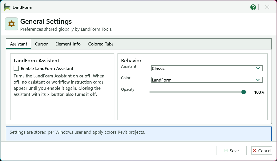
Switch between the four groups of settings; this picture shows the Assistant tab.
Shows the assistant and its workflow instruction cards while a tool runs; clear it to hide them everywhere.
Chooses the assistant persona, Classic or Lady.
Chooses the colour of the assistant cards: LandForm, Random palette or a single colour such as Blue or Olive.
Sets how opaque the assistant cards are, from 45% to 100%.
Reminds you that every choice is saved for your Windows user and applies in every Revit project.
Saves every setting and applies the Assistant, hover card and Colored Tabs changes at once.
Closes the window without changing any setting.
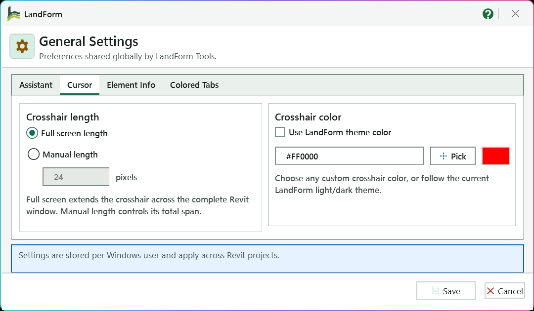
Opens the settings for the pick crosshair's length and colour.
Stretches the pick crosshair across the whole Revit window.
Limits the crosshair to the total span typed in the box, from 24 to 2000 pixels.
Colours the crosshair to follow the light or dark theme; clear it to use a custom colour.
Type the hex colour of the crosshair when the theme colour is not used.
Opens the colour picker for the crosshair colour.
Shows the crosshair colour that will be used.
Saves every setting for the current Windows user.
Closes the window without changing any setting.
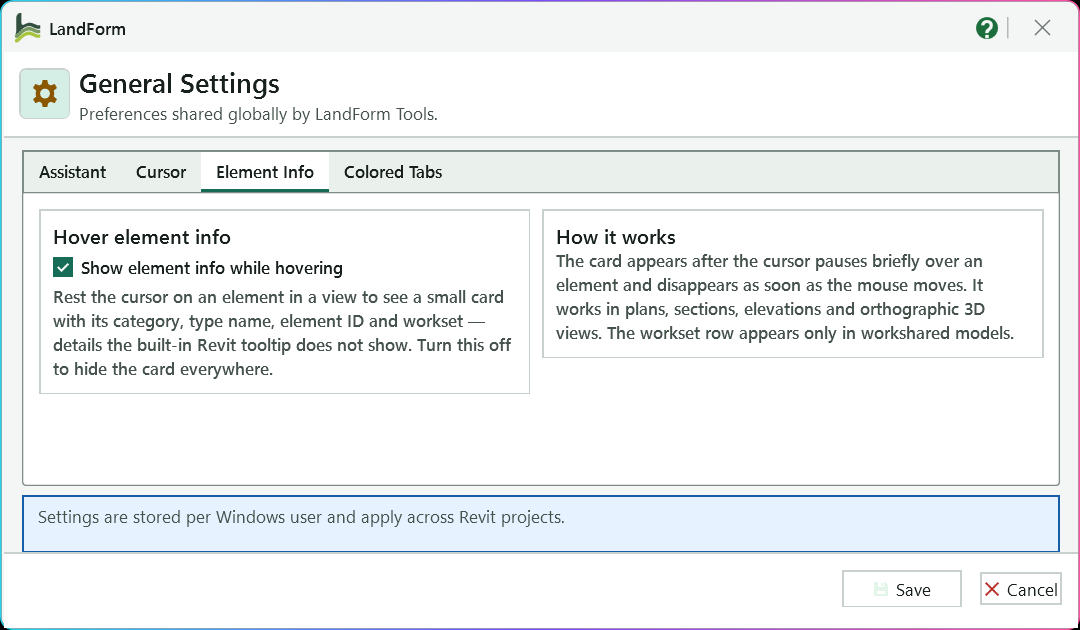
Opens the setting for the hover element card.
Shows a small card with the category, type name, element ID and workset of the element under a resting cursor; clear it to hide the card everywhere.
Explains when the card appears and that it works in plans, sections, elevations and orthographic 3D views.
Reminds you that the choice is saved for your Windows user and applies in every Revit project.
Saves the settings and switches the hover card on or off at once.
Closes the window without changing any setting.
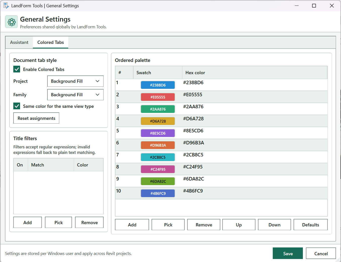
Opens the settings that colour Revit's view tabs.
Colours Revit's document tabs with the chosen style and palette; clear it to restore the standard tabs.
Style for project view tabs: a top bar or a border in four weights, or Background Fill.
Style for family document tabs, with the same choices.
Each view gives every tab its own colour, Same view type shares one per kind of view, and Same opened model shares one per project or family.
Forgets the colour each open tab was given so colours are dealt out again from the palette.
The colours the tabs cycle through, with a swatch and an editable hex value per row; double-click a row to pick its colour.
Appends a colour to the palette.
Opens the colour picker for the selected row.
Deletes the selected colour.
Move the selected colour one place earlier or later in the order.
Restores the standard ten colours, styles and grouping; Enable Colored Tabs is kept.
Saves the settings and recolours open view tabs straight away.
Closes the window without changing any setting.
Open LandForm tab → About panel → LandForm ▾ → Settings.
Assistant. On the Assistant tab, tick Enable LandForm Assistant to show the assistant and its workflow instruction cards while a tool runs, or clear it to hide them everywhere. Under Behavior, choose the Assistant persona (Classic or Lady), the card Color (LandForm, Random palette, Blue, Olive, Plum, Amber or Gray) and the Opacity of the cards, from 45% to 100%.
Closing the assistant with its own × button also turns this setting off.
Cursor. On the Cursor tab, pick Full screen length to stretch the pick crosshair across the whole Revit window, or Manual length and type its total span in pixels (24 to 2000). Tick Use LandForm theme color to follow the light or dark theme, or clear it and type a hex colour or press Pick to choose one; the swatch shows the result.
Element Info. On the Element Info tab, tick Show element info while hovering to get a small card with the category, type name, element ID and workset of the element under a resting cursor. It works in plans, sections, elevations and orthographic 3D views; clear the box to hide the card everywhere.
Colored Tabs. On the Colored Tabs tab, tick Enable Colored Tabs, then choose a style for Project tabs and for Family tabs: a top bar or a border in four weights, or Background Fill. Under Color by, choose Each view for a different colour per tab, Same view type to share a colour across all plans, all sections and so on, or Same opened model to colour every tab of one project or family alike.
Reset assignments forgets which colour each open tab was given so they are dealt out again from the palette.
Title filters (optional). Press Add under Title filters to create a rule, type the text or regular expression a tab title must match in Match, and set its Color by typing a hex value, pressing Pick or double-clicking the row. Clear On to pause a rule, or select it and press Remove.
An invalid regular expression falls back to plain text matching.
Ordered palette. Edit the colours the tabs cycle through: Add appends a colour, Pick (or a double-click) opens the colour picker for the selected row, Remove deletes it, Up and Down change the order, and Defaults restores the standard ten colours.
Save. Press Save. The Assistant, hover card and Colored Tabs settings take effect immediately; Cancel leaves everything as it was.
Your choices are written to a settings file for the current Windows user and used by every LandForm tool in every Revit project. The Assistant and hover card switch on or off at once, and open view tabs are recoloured straight away when Colored Tabs is enabled. Reopen the window at any time to adjust them.
Sheet can give every sheet tab one fixed colour while other tabs keep cycling.Shows the LandForm Assistant settings: the on/off switch, persona, card colour and opacity.
Turns the LandForm Assistant and its workflow instruction cards on or off for every tool. Closing the assistant with its × button also turns it off.
Chooses the assistant persona: Classic or Lady.
Chooses the colour scheme of the assistant cards: LandForm, Random palette, Blue, Olive, Plum, Amber or Gray.
Sets how opaque the assistant cards are, from 45% to 100%.
Shows the pick crosshair settings: its length and colour.
Extends the crosshair across the complete Revit window.
Limits the crosshair to the span typed in the length box.
Total crosshair span in pixels (24 to 2000) when Manual length is selected.
Colours the crosshair to match the current LandForm light or dark theme instead of a custom colour.
Hex colour of the crosshair, for example #A6ECFF, when the theme colour is not used.
Opens the colour picker for the crosshair colour.
Shows the hover element card setting.
Shows a card with category, type name, element ID and workset when the cursor rests on an element; clear it to hide the card everywhere.
Transient preview graphics options. This tab is hidden in the current window.
Chooses between standard Autodesk graphics and the fast LandForm preview for transient previews (hidden tab).
Uses Autodesk's default colour for preview points instead of a custom one (hidden tab).
Hex colour of preview points when the default colour is not used (hidden tab).
Opens the colour picker for the preview point colour (hidden tab).
Shows the Colored Tabs settings: tab style, colour grouping, title filters and the palette.
Colours Revit's document tabs with the chosen style and palette; clear it to restore the standard tabs.
Style applied to project view tabs: Top Bar or Border in Light, Medium, Heavy or Heavier weight, or Background Fill.
Style applied to family document tabs, with the same choices as the project style.
Each view gives every tab its own colour. Same view type shares a colour across plans, sections, and so on. Same opened model shares a colour across every tab of one project or family.
Forgets the colour given to each open tab so colours are dealt out again from the palette.
Title filter rules: On, the Match text or regular expression, and the Color a matching tab gets. Double-click a row to pick its colour.
Adds a new title filter rule to the list.
Removes the selected title filter rule.
The ordered colours that tabs cycle through, with a swatch and editable hex value per row. Double-click a row to pick its colour.
Moves the selected palette colour one place earlier in the order.
Moves the selected palette colour one place later in the order.
Restores the standard palette, styles and grouping; the Enable Colored Tabs setting is kept.
Saves every setting for the current Windows user and applies the Assistant, hover card and Colored Tabs changes at once.
Closes the window without changing any setting.

About · LandForm · License
LandForm is sold as a one-year subscription; there is no trial. The License window shows the state of the computer you are on, a button to the place where the subscription is sold, and a field for a license key. On a computer that is not yet licensed the LandForm tab shows only this button, so the way to subscribe is always one click away. On a licensed computer the window confirms the license and lets you move the computer to a different key.
LandForm tab→About panel→LandForm ▾→License
Button tooltip: “Open the LandForm license window.”LF-XXXX-XXXX-XXXX.License walkthrough. Until it is published, the steps and the annotated window below walk through the same workflow.
Numbers on the screenshot match the legend. Hover a number or a legend row to highlight the other.
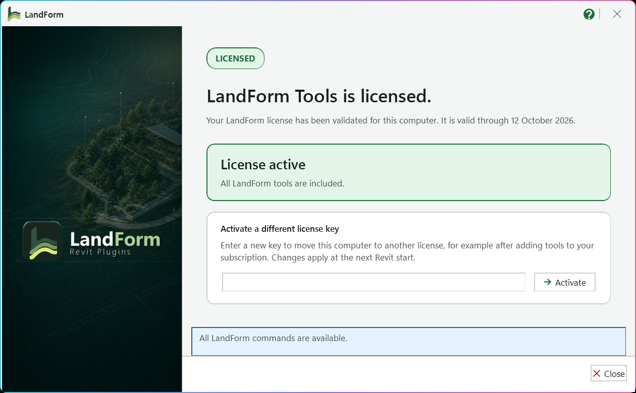
The badge tells you where the computer stands, for example LICENSE REQUIRED, LICENSE EXPIRED or RE-VALIDATION NEEDED.
Says how the computer is licensed; for a LandForm key it shows the date the license is valid through.
Confirms the tools are available and whether all tools are included or some are greyed out on the ribbon.
Paste a key in the form LF-XXXX-XXXX-XXXX to move this computer to another license; letters become upper case as you type.
Redeems the key with the license service (or press Enter); the tools change at the next Revit start.
Status line; during an activation it reports the contact with the license service, then the error or the new status.
Closes the window.
Open LandForm tab → About panel → LandForm ▾ → License.
Read the status. The badge at the top tells you where the computer stands: LICENSED, LICENSE REQUIRED, LICENSE EXPIRED, LICENSE DISABLED, RE-VALIDATION NEEDED or, just after an activation, ACTIVATED. The card below says whether the tools are available and, for a licensed computer, whether all tools are included or some are greyed out on the ribbon.
A licensed computer also shows how it is licensed: an Autodesk App Store subscription verified for the Autodesk Account signed in to Revit, or a LandForm license valid through a given date.
Subscribe. When a license is required or has expired, the purchase card names the shop for the one-year subscription and the Buy on … button opens it in your browser. The App Store edition sends you to the LandForm listing on the Autodesk App Store, where the subscription is verified automatically with the Autodesk Account you use in Revit. The website edition sends you to landformautomation.com, and the license key arrives by email.
Email support opens a message to LandForm with the computer name already in the subject line.
Activate a key. Paste the key into the License key field and press Activate (or Enter). The window reports "Contacting the license service..." and then either the error the service returned or the new status.
Restart Revit. After a successful activation, a verified subscription or a successful Check again, the badge reads ACTIVATED and the window asks you to restart Revit. The LandForm ribbon is built when Revit starts, so the tools appear after the next start.
Check again. If the status says the license service could not be reached, press Check again in the footer; the window also re-checks on its own when the startup check did not get an answer. Press Close when you are done.
Once the computer is licensed, Revit starts with the full LandForm tab and the License window confirms LICENSED with the source of the license and, for a key, its end date. A signed copy of the last answer from the license service is kept on the computer, so LandForm keeps working for up to 14 days without a connection; after that the window shows RE-VALIDATION NEEDED until you reconnect and restart Revit.
Opens the shop for the one-year subscription in your browser: the Autodesk App Store listing in the App Store edition, landformautomation.com in the website edition. Shown while a license is required or expired.
Opens a new email to LandForm support with the computer name in the subject.
The key from your purchase, license or renewal email (LF-XXXX-XXXX-XXXX). Letters are converted to upper case as you type.
Redeems the key for this computer with the license service and shows the new status; the tools load at the next Revit start.
Asks the license service for a fresh answer. Shown only while the computer is not licensed.
Closes the window.
LandForm ribbon panel
Shape the ground: studio editing, mounds and point sculpting on toposolids.

Terrain · Terrain Studio
Terrain Studio is where you shape ground the way you would on a physical model: brush the surface up and down, drop in level pads, run graded paths across a slope and pin contours at fixed levels. Every change is a preview until you press Save to Revit, so you can try, undo and compare freely. When you save, LandForm writes the new heights into the original element, keeps a cut and fill history on it, and can create new Toposolids where you asked for them.
LandForm tab→Terrain panel→Terrain Studio
Button tooltip: “Sculpt and grade terrain in a dockable 3D editor with live contours.”Terrain Studio walkthrough. Until it is published, the steps and the annotated window below walk through the same workflow.
Numbers on the screenshot match the legend. Hover a number or a legend row to highlight the other.
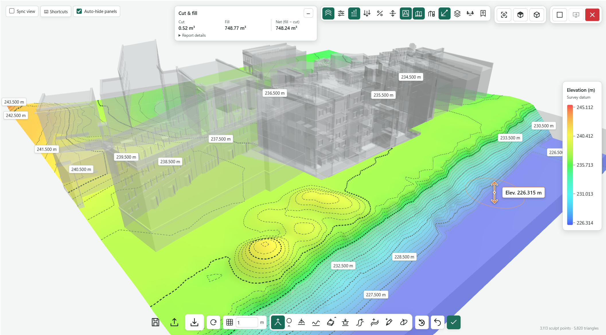
Sets how far apart the new points are under each brush stroke.
The tool buttons: Sculpt, brush settings, Flatten, Smooth, Add pad, Cutter, Add path, Add contour, Outline and Orbit.
Drag upward on the terrain to raise it or downward to lower it; [ and ] resize the brush.
Switches on contours, the heatmap, flow and slope arrows, labels, CAD guides, Section cut and Saved views.
Colour scale for the elevation heatmap, from the lowest to the highest ground.
Live cut, fill and net volume for the current edits, with History once the surface has saved revisions.
Clears every unsaved edit, or steps back one edit.
Writes the new heights into the original element (Ctrl+Enter); larger edits offer a choice of routes.
Discards unsaved edits and reads the surface from Revit again.
Save, load or compare a design, export the terrain, or import a saved study as a new Toposolid.
Zoom extents, top view and 3D view.
Follow the active Revit 3D view, change the keyboard shortcuts, and collapse the tool settings while you orbit or zoom.
Open LandForm tab → Terrain panel → Terrain Studio.
Load the surfaces. Start the tool with the surfaces selected, or choose Pick one surface or All visible floors and Toposolids in the dialog. LandForm reads the geometry and opens the studio over the Revit view, with the rest of the view ghosted around the terrain for context.
With several surfaces loaded they edit as one mesh: a stroke or grading design changes whichever surface lies under it.
Sculpt by hand. Choose Sculpt in the bottom action strip and drag upward on the terrain to raise it or downward to lower it. Open the brush settings next to it to set Brush radius (m) and the shape (Circle, Oval, Rectangle, Square); [ and ] resize the brush and Space rotates it by 15°.
Flatten pulls the ground under the brush to the picked level, and Smooth evens out a rough patch. The m box at the left of the strip is the brush grid spacing.
Add a pad. Choose Add pad, pick a Pad shape (closed polyline, circle, rectangle, square or a single spot level) and click it on the terrain, or use Pick from Revit to follow a model or detail line. Enter the Pad elevation (m), choose how the Surrounding terrain meets it (Cut / fill embankment, Smooth transition or Straight cut · vertical sides) and set the cut and fill slopes. Press Add pad to stage it.
Cutter opens the same tool already set to a straight cut, for a flat excavation with vertical sides.
Add a path. Choose Add path, click the route points and right-click to finish. Set the Centerline (polyline, smooth curve or tangent arcs), Path width (m), shoulders and Crossfall (%), then pick a Grade control: a fixed slope, an end elevation, follow the terrain, or a Design profile you edit in the profile window. Press Add path.
Turn on Auto-join intersecting paths to blend crossings and T-junctions into paths you have already drawn.
Hold a contour. Choose Add contour, draw the line, give it a Contour elevation (m) or click individual point labels to give points their own heights, set the Influence width each side (m) and press Add contour. The ground grades between the contour and the existing terrain across that width.
Check the design. Use the display toolbar along the top to switch on contours, the elevation heatmap, downhill flow arrows or slope grade arrows (amber below the minimum, red above the maximum you set). The Cut & fill card shows cut, fill and net volume for the current edits. Open Section cut and press Draw section line to cut through the terrain; 2D section shows the same cut at true scale.
Save to Revit. Press Save to Revit (Ctrl+Enter). Sculpting and small edits are written straight away, changing only the touched points. For larger edits a chooser opens with the recommended route first; see the section below. A progress bar runs while Revit works, then the studio closes and an Apply complete notice summarises what was written.
Prefer New Toposolid when you want a fresh element built from the preview and the source left untouched.
The edited Floors and Toposolids carry the new shape as their own points, so Revit's shape-editing tools still work on them. Points Revit refuses are skipped and listed in the completion notice instead of cancelling the whole save. Each save adds a revision to the surface's cut and fill history and fills the LF_Terrain parameters on the element (for example LF_Terrain Cut Volume, LF_Terrain Fill Volume, LF_Terrain Net Volume and the overall totals since the first tracked save), with schedules named LF Terrain - Cut and Fill - … and LF Terrain - Cut and Fill History added to the project. With several surfaces loaded, the whole save is one Undo step named "LF-Terrain Studio: Apply Changes to … Surfaces".
No separate LandForm window. This command runs directly from Revit selection and prompts; follow the workflow above and the messages shown beside the cursor or on Revit's status bar.

Terrain · Mounds · Mound Factory
Mound Factory is the quickest way to add a berm, a play mound, a planting hill or a shallow swale to existing terrain. You choose a plan silhouette and a section profile, set the size with three numbers, watch the point field preview over the surface, and press Apply. The result is editable Revit geometry: LandForm adds shape points to the surface, so Revit's own tools still work afterwards.
LandForm tab→Terrain panel→Mounds ▾→Mound Factory
Button tooltip: “Create preset landscape mounds or depressions on an editable surface.”Mound Factory walkthrough. Until it is published, the steps and the annotated window below walk through the same workflow.
Numbers on the screenshot match the legend. Hover a number or a legend row to highlight the other.

Click it, then click the toposolid or floor where the mound centre should be.
Tells you what to pick next; here it asks for a surface and a snapped mound centre.
The plan silhouette. Press Space to rotate a non-circular shape in 15° steps.
Returns to Revit to pick model lines or a filled region whose outline becomes the Custom shape.
Mound width in metres. Long-press and drag vertically to scrub the value.
Summit height in metres; a negative value makes a depression.
Distance between the surface points that will be added, in metres.
The section shape, such as a soft Sphere dome or a flat-topped plateau.
Opens the current profile in the live section window so you can reshape it.
Redraws the point-field preview without changing the model.
Shows the summit-grip commands; Bezier Base shows the base anchors for reshaping the outline.
Adds the previewed mound to the surface as shape points in one undo step.
How many points the mound adds.
Opens the keyboard shortcut settings for size, preview, pick and apply.
Open LandForm tab → Terrain panel → Mounds ▾ → Mound Factory.
Pick the location. Click Move / Pick Location, then click the toposolid or floor where the mound centre should be. The toolbar reappears and the status line confirms the surface.
Choose the plan shape. Open Shape and pick a preset, or choose Custom and trace an outline you have already drawn as model lines or a filled region.
Press Space to rotate a non-circular shape in 15° steps.
Set the size. Enter Diameter, Height and Spacing. Long-press any of the three boxes and drag vertically to scrub the value while the preview follows.
Use a negative Height to make a depression.
Choose the profile. Open Profile and pick the section shape. Sphere gives a soft dome; a plateau profile keeps a flat top for seating or play equipment.
Preview. Press Preview and look at the point field on screen. Switch to a 3D view if you want to judge the height against nearby elements; the preview is redrawn when you change a value.
Refine with grips (optional). Turn on Grips to show the summit grips, then use + Grip, Set Height and Select Grips to raise or lower parts of the mound. Turn on Bezier Base to drag the base anchors and reshape the outline.
Apply. Press Apply. LandForm adds the shape points to the surface in one undoable step named "LF-Mound Factory: Apply".
The toposolid or floor now carries the mound as native shape points, with the summit at the height you entered and the base blending into the existing surface at the chosen diameter. The point count on the status line tells you how many points were added. Revit's own Modify Sub Elements tools, Smooth Mound and Point Grip can all edit it further.
Opens the Mound keyboard shortcut settings.
Chooses the plan silhouette, or Pick Outline to trace a custom outline from the model. Press ` to cycle the presets.
Returns to Revit so you can pick model lines or a filled region; their outline becomes the Custom plan silhouette.
Returns to Revit so you can click the surface and set the mound centre.
Mound diameter in metres. Type a value or long-press and drag vertically to scrub it.
Mound height in metres; negative values make a depression. Type a value or long-press and drag vertically.
Distance between the surface points that will be added, in metres. Type a value or long-press and drag vertically.
Shows the summit-grip commands (+ Grip, − Grip, Set Height, Select Grips) on the contextual row.
Shows the base anchors. Dragging an anchor reshapes the closed Bezier outline with automatic smooth tangents.
Chooses a standard or fixed section profile for the mound.
Opens the current profile in the shared live section window so you can reshape it.
Redraws the point-field preview without changing the model.
Writes the previewed mound to the selected surface as shape points.
Closes Mound Factory and removes the preview.
Pick a point on the mound to insert a summit grip there.
Removes the selected summit grip.
Applies the Height value to the selected summit grips.
Elevation of the selected summit grip in metres above the Project Base Point. Type a value to move the grip there; select grips with Tab or by picking them.
Selects several summit grips with hover highlighting.
Inserts a Bezier base anchor at the closest point on the outline.
Key that decreases Diameter by one step. Backspace or Delete sets it to Off.
Key that increases Diameter by one step. Backspace or Delete sets it to Off.
Key that decreases Height by one step. Backspace or Delete sets it to Off.
Key that increases Height by one step. Backspace or Delete sets it to Off.
Key that decreases Spacing by one step. Backspace or Delete sets it to Off.
Key that increases Spacing by one step. Backspace or Delete sets it to Off.
Key that starts Move / Pick Location. Backspace or Delete sets it to Off.
Key that refreshes the preview. Backspace or Delete sets it to Off.
Key that applies the mound. Backspace or Delete sets it to Off.
Restores every shortcut to its default key.
Saves the shortcuts and returns to the toolbar.

Terrain · Mounds · Smooth Mound
Smooth Mound is for landforms that follow a line rather than sit on a point: a berm along a boundary, a curving bund, a long play mound or a shallow ridge that screens a car park. You click the stations of the path directly on the surface, raise or lower each one, choose how the section falls away from the crest to the edge of the surface, and watch a live preview of points or contours. Pressing Run writes the result into the surface as native shape points, so Revit's own Modify Sub Elements tools still work afterwards.
LandForm tab→Terrain panel→Mounds ▾→Smooth Mound
Button tooltip: “Shape a surface from an editable station path.”Smooth Mound walkthrough. Until it is published, the steps and the annotated window below walk through the same workflow.
Numbers on the screenshot match the legend. Hover a number or a legend row to highlight the other.

Tells you the next step, then what the preview contains and how many shape points were written.
Height of the selected station in metres above the Project Base Point; the arrows nudge it by 0.10 m.
Click the surface to insert a station on the nearest segment, or remove the selected one.
The section from crest to boundary: Arc, Bezier, Half Sphere or Plateau.
Opens the live section window, where you drag the curve to change fullness, shoulder width or chamfer.
Distance between the shape points that will be written, in metres.
Shows the preview as Points or Isolines.
Contour interval of the Isolines preview; active only while View is Isolines.
How many stations the path has and how many points the preview contains.
Rebuilds the surface from the preview in one undoable step; it then reads Run Again.
Shows or changes every keyboard shortcut.
Open LandForm tab → Terrain panel → Mounds ▾ → Smooth Mound.
Pick the surface. The pick starts as soon as the toolbar opens: click the toposolid or floor you want to shape. The status line changes from "Step 1" to "Step 2" and the surface boundary is highlighted.
If you shaped this surface with Smooth Mound before, the previous path and settings are restored from the surface and you can carry on editing them.
Draw the path. Click the stations of the crest line on the surface, one after another, then press Esc to finish. At least two stations are needed; the draft line appears after the second click.
To start the line again later, press the Draw path shortcut (Ctrl+Alt+D by default) and click a new set of stations.
Set station heights. Each station gets an adaptive point grip in the model with an elevation chip beside it. Select a station by clicking its grip, or step through them with Tab and Shift+Tab, then type its level in the Z box, nudge it with the arrows (0.10 m per step), or click the chip on screen and type the exact value.
Z is metres above the Project Base Point, so the numbers match Revit spot elevations.
Move, add or remove stations. Drag a grip with Revit's own Move tool to shift a station in plan or height; the preview follows. Press + and click the surface to insert a station on the nearest segment of the path, or − to remove the selected one (the path always keeps at least two).
Choose the section. Open Profile and pick Arc, Bezier, Half Sphere or Plateau. Press Edit to open the live section window, where you drag the curve or its grips to change the fullness, shoulder width or chamfer; the toolbar follows your changes.
Set the grid and the preview. Enter Spacing, the distance between the shape points that will be written (0.05 to 20 m). Under View, choose Points to see the point field or Isolines to see contours at the Contours interval you enter.
The preview redraws itself about a third of a second after every change; the status line and the "stations | points" counter tell you what it contains.
Run. Press Run (or Ctrl+Alt+Enter). LandForm generates the final point field at your spacing and rebuilds the surface in one undoable step named "LF-Smooth Mound: Apply Shape". When it finishes, the status line reports how many shape points were written and the button changes to Run Again, which starts a fresh surface pick.
The toposolid or floor now carries the ridge as native shape points: the crest runs through your stations at the heights you set, and the section you chose falls away to the surface boundary, which keeps its original levels. The path and its settings are stored on the surface, so running Smooth Mound on it again reloads them for further editing. Revit's Undo removes the whole rebuild in one step, and Point Grip or Modify Sub Elements can refine the result.
Opens the Smooth Mound keyboard shortcut settings.
Pick a point on the surface to insert a station on the nearest path segment. Use Keys to edit its shortcut.
Removes the selected station. At least two stations are retained. Use Keys to edit its shortcut.
Elevation of the selected station in metres above the Project Base Point. Typing a value moves the station and refreshes the preview.
Raises the selected station by 0.10 m.
Lowers the selected station by 0.10 m.
Distance between the shape points that will be written, in metres (0.05 to 20).
Increases Spacing by 0.05 m.
Decreases Spacing by 0.05 m.
Chooses the cross-section curve from the crest to the surface boundary: Arc, Bezier, Half Sphere or Plateau.
Opens the live Mound Profile window, where dragging the curve or its grips adjusts fullness, plateau width or chamfer.
Contour interval of the Isolines preview, in metres (0.05 to 20). Active only when View is Isolines.
Increases the contour interval by 0.05 m.
Decreases the contour interval by 0.05 m.
Chooses whether the preview shows the generated points or isolines.
Writes the previewed surface to the selected host as shape points. Reads Run Again after a rebuild, which starts a new surface pick. Use Keys to edit its shortcut.
Closes Smooth Mound and removes the preview and station grips.
Key that selects the previous station (default Shift+Tab). Backspace or Delete sets it to Off.
Key that selects the next station (default Tab). Backspace or Delete sets it to Off.
Key that lowers the selected station by 0.10 m (default Ctrl+Alt+Down). Backspace or Delete sets it to Off.
Key that raises the selected station by 0.10 m (default Ctrl+Alt+Up). Backspace or Delete sets it to Off.
Key that decreases Spacing by 0.05 m (default Ctrl+Alt+Shift+S). Backspace or Delete sets it to Off.
Key that increases Spacing by 0.05 m (default Ctrl+Alt+S). Backspace or Delete sets it to Off.
Key that decreases the contour interval by 0.05 m (default Ctrl+Alt+Shift+C). Backspace or Delete sets it to Off.
Key that increases the contour interval by 0.05 m (default Ctrl+Alt+C). Backspace or Delete sets it to Off.
Key that starts the add-station pick (default Ctrl+Alt++). Backspace or Delete sets it to Off.
Key that removes the selected station (default Ctrl+Alt+-). Backspace or Delete sets it to Off.
Key that starts drawing a new path on the surface (default Ctrl+Alt+D). Backspace or Delete sets it to Off.
Key that lets you click a new plan location for the selected station (default Ctrl+Alt+M). Backspace or Delete sets it to Off.
Key that refreshes the preview (default Ctrl+Alt+P). Backspace or Delete sets it to Off.
Key that runs the surface rebuild (default Ctrl+Alt+Enter). Backspace or Delete sets it to Off.
Restores every shortcut to its default key.
Saves the shortcuts and returns to the toolbar.

Terrain · Auto Mound · Auto Mound
Auto Mound is the fastest way to make a berm or planting mound. There is no path to draw: the tool reads the outline, derives an end-to-end axis with a few grips on it, and shows a live isoline preview at the Height you set. After you pick the surface, Auto Mound asks for the outline the mound rises from. Pick another floor, toposolid or subdivision on it and only that part of the surface is shaped, or click the same surface again to mound all of it. Base switches the outline to a loop of picked edges or lines, or one you draw. Tick Invert and the same shape becomes a pond, basin or swale. Nothing is written to the model until you press Run.
LandForm tab→Terrain panel→Auto Mound ▾→Auto Mound
Button tooltip: “Create an automatic mound fitted to an editable surface boundary.”Auto Mound walkthrough. Until it is published, the steps and the annotated window below walk through the same workflow.
Numbers on the screenshot match the legend. Hover a number or a legend row to highlight the other.

The status line; click the floor or toposolid to turn into a mound.
The summit height; the arrows step it by 0.10 m.
Change the number of axis grips and redistribute the arc evenly along the axis.
The cross-section from the axis to the boundary: Arc, Bezier, Half Sphere or Plateau.
Opens the live section window to adjust the profile curve.
Sinks the shape below the surface for a pond, basin or swale.
Distance between the shape points LandForm will add.
Shows the preview as Isolines or Points.
Counts the axis stations and shape points in the current preview.
Writes the previewed mound to the surface in one undoable step.
Open LandForm tab → Terrain panel → Auto Mound ▾ → Auto Mound.
Pick the surface. Revit asks you to select the floor or toposolid to shape as soon as the toolbar opens.
A surface that already carries an Auto Mound reloads its saved settings.
Pick the base outline. Revit then asks for the outline the mound rises from. Click a floor, toposolid, toposolid subdivision or filled region on the surface, and only the area inside its outline is shaped. Click the same surface again to mound all of it instead. Base then reads Whole surface. LandForm places the axis with five grips and draws the preview straight away.
To outline the base another way, change Base and the matching pick starts at once. With Picked edges, click model edges that go all the way round, then Finish. With Model lines, select model lines, detail lines or a filled region that form a closed outline, then Finish. With Drawn outline, click the corners on the surface, then click the first corner again or press Esc to close it. The outline is laid onto the surface and trimmed to its edge, and the axis and grips are worked out from it. The button beside Base picks the outline again. Auto Mound keeps an outline method for the next mound in the same Revit session. A new session always starts with the outline pick, so Auto Mound never reshapes a whole surface unless you click it.
Set the height. Type the summit height in Height, step it by 0.10 m with the arrows, or press - and + while the toolbar is open. The preview refreshes a moment after each change.
Shape the axis. Drag any grip in the model to move the axis or change its height there; the preview follows. Add grip and Remove grip change the number of grips and redistribute the arc evenly along the axis. An elongated surface keeps at least three grips; a circular one has a single centre grip.
Choose the section. Profile sets the cross-section from the axis down to the boundary: Arc, Bezier, Half Sphere (the default) or Plateau. Press Edit to adjust the curve in the live section window.
Invert for a depression (optional). Tick Invert to sink the shape below the surface by the same height. The grips flip through the surface and keep any manual edits you made.
Set the density and preview style. Spacing is the distance between the shape points LandForm will add. Display switches the preview between Isolines (drawn at 0.10 m intervals) and Points.
Run. Press Run. LandForm writes the mound in one undoable step named "LF-Auto Mound: Apply Shape" and reports how many shape points it added. The button then reads Run Again, which starts another surface pick. To add another mound to the same surface, choose or re-pick a Base instead.
The surface is now a mound, or a basin if you inverted it, whose summit line runs along the derived axis at the height you set and falls to the existing boundary elevation with the profile you chose. With a Base outline, only the area inside it changes. The mound rises from the existing ground, sloped or not, and everything outside the outline keeps its shape points and elevations. A ring of points just outside the outline holds the ground there. The settings are stored on the element, so re-running Auto Mound on the same surface reloads them. The points are native shape points, so Revit's Modify Sub Elements tools keep working on them.
Adds an axis grip and redistributes the arc evenly along the axis.
Removes an axis grip and redistributes the arc. An elongated surface keeps at least three grips; a circular surface keeps its single centre grip.
What the mound rises from: Whole surface, Floor / toposolid, Picked edges, Model lines or Drawn outline. Choosing an outline starts its pick.
Picks the base outline again with the current Base method.
Maximum mound height in metres, 0.05 m or more. The arrows and the - / + keys step it by 0.10 m.
Distance in metres between the shape points used for the preview and the final mound.
Increases Spacing by 0.05 m.
Decreases Spacing by 0.05 m.
Cross-section from the axis to the boundary: Arc, Bezier, Half Sphere or Plateau.
Opens the live section window to shape the selected profile; the preview follows.
Sink the shape below the surface by the Height instead of raising it, for a pond, basin or swale. The grips flip through the surface and keep any manual edits.
Shows the preview as Isolines or as generated Points.
Writes the previewed mound to the selected surface as shape points. Reads Run Again afterwards to start on another surface.
Closes Auto Mound and removes the preview.
Terrain · Auto Mound · Composite Mound
Use Composite Mound when a mound has to cross a boundary you cannot remove: a berm that spans two toposolids, or a planting hill shared between a floor and the terrain around it. LandForm combines the outer extents of the surfaces you select, derives one end-to-end axis for the whole area and previews a single point field across all of them. When you press Run it builds a temporary mound, drapes every selected surface onto it and removes the temporary geometry again.
LandForm tab→Terrain panel→Auto Mound ▾→Composite Mound
Button tooltip: “Create one automatic mound across several editable surfaces.”Composite Mound walkthrough. Until it is published, the steps and the annotated window below walk through the same workflow.
Numbers on the screenshot match the legend. Hover a number or a legend row to highlight the other.

Status line; it asks you to select the touching floors or toposolids, and after Run reports how many surfaces were draped.
Counts of the axis grips and of the preview points.
Summit height in metres; the arrows or the - and + keys step it by 0.10 m.
Add grip and Remove grip change how many axis grips there are; the arc is redistributed evenly each time.
Cross-section from the axis to the boundary: Arc, Bezier, Half Sphere or Plateau.
Opens the live section window to shape the selected profile.
Sinks the shape below the surfaces by the same height, for a basin.
Distance in metres between the shape points written to every selected surface.
Drapes every selected surface onto the previewed mound and writes the shape points.
Open LandForm tab → Terrain panel → Auto Mound ▾ → Composite Mound.
Select the surfaces. Revit asks you to select touching floors or toposolids. Click each one and finish the selection. If fewer than two are picked the status line asks you to select again. LandForm estimates the combined outer boundary, places the axis with five grips and shows a point preview across every surface.
Set the height. Type the summit height in Height, or step it by 0.10 m with the arrows or the - and + keys. The preview refreshes a moment later.
Shape the axis. Drag the grips in the model to move the axis or change its height, or use Add grip and Remove grip to change how many there are. The arc is redistributed evenly each time.
Choose the section. Profile picks the cross-section from the axis to the boundary: Arc, Bezier, Half Sphere or Plateau. Edit opens the live section window.
Invert for a basin (optional). Tick Invert to sink the shape below the surfaces by the same height while keeping any grip edits.
Set the spacing. Spacing controls the point grid written to each surface. Composite Mound always previews points; there is no isoline display here.
Run. Press Run. LandForm creates the temporary mound, drapes each selected surface onto it, verifies the requested grid on every surface and deletes the temporary mound. The status line reports how many surfaces were draped and how many shape points were written.
Each selected floor or toposolid now carries its share of the mound as native shape points, and together they form one continuous surface across the joint. The elements are not joined or replaced; each keeps its own type, level and boundary. A surface that did not overlap the mound is left unchanged and named in the status line. The whole run is one Revit undo group, "LF-Composite Mound: Create Mound".
Adds an axis grip and redistributes the arc evenly along the axis.
Removes an axis grip and redistributes the arc; at least three grips are kept.
Maximum mound height in metres, 0.05 m or more. The arrows and the - / + keys step it by 0.10 m.
Distance in metres between the shape points written to every selected surface.
Increases Spacing by 0.05 m.
Decreases Spacing by 0.05 m.
Cross-section from the axis to the combined boundary: Arc, Bezier, Half Sphere or Plateau.
Opens the live section window to shape the selected profile; the preview follows.
Sink the shape below the surface by the Height instead of raising it, for a pond, basin or swale. The grips flip through the surface and keep any manual edits.
Hidden in Composite Mound; the preview always shows points.
Drapes every selected surface onto the previewed mound and writes the shape points.
Closes Composite Mound and removes the preview.

Terrain · Sculpt Terrain · Point Grip
Point Grip is the quick way to shape a surface locally without drawing an outline first. Every click places a grip, called a station in the toolbar, that pushes the surface up (or pulls it down) within a round, oval or rectangular footprint. You see the result straight away as a preview of points and contours, adjust the grips from the toolbar or by dragging them in the model, and press Apply when the shape is right. Grips can also be chained into one continuous ridge with Connect grips.
LandForm tab→Terrain panel→Sculpt Terrain ▾→Point Grip
Button tooltip: “Create local terrain mounds from manually placed adaptive point grips.”Point Grip walkthrough. Until it is published, the steps and the annotated window below walk through the same workflow.
Numbers on the screenshot match the legend. Hover a number or a legend row to highlight the other.

+ picks more stations and − removes the selected one; the counter shows which station is selected.
Peak level of the selected grip in metres above the Project Base Point; below the surface it makes a hollow.
Diameter of the selected grip's footprint, in metres.
Reminds you of the keys that step the height and the diameter by 0.10 m.
Footprint of the selected grip: Round, Oval or Rectangle.
Second diameter and rotation for Oval and Rectangle footprints; greyed out for Round.
Chooses the section (Arc, Bezier, Half Sphere or Plateau); Edit shapes it in the live profile window.
Distance between the points that will be written, in metres (minimum 0.10).
Shows the preview as Points, Contours or Points + Contours.
Spacing of the preview contours, in metres.
Locks the outer edge of the surface at its current heights.
Blends all stations, in the order you placed them, into one smooth ridge.
Writes the mounds to the surface as shape points and keeps the toolbar open.
Confirms when the preview has been rebuilt and reports how many points were written.
Open LandForm tab → Terrain panel → Sculpt Terrain ▾ → Point Grip.
Place the first grip. Click a point on the toposolid or floor where the first peak should be. The toolbar opens with Station 1 / 1, the preview appears around the point, and Revit keeps asking for more points.
Add more grips. Keep clicking the same surface to add stations; each new grip takes the height, diameter and shape of the selected one and becomes the selection. Press Esc when you have placed enough.
Press + at any time to pick more stations, and − to remove the selected one (the last remaining grip cannot be removed).
Set the selected grip. Click a grip in the model to select it, then type its peak level in Z (metres above the Project Base Point) or step it with the arrows, - and +. Set the footprint with D (arrows, [ and ]). Choose Oval or Rectangle under Shape to unlock D2, the second diameter, and Angle, the rotation in 5° steps.
A Z below the surface pulls the ground down instead of raising it, which makes a hollow or pond. Each grip also shows an elevation chip in the view; click the chip to type the level in place.
Move grips in the model. Drag a grip with Revit's Move tool, or select it and move it, to shift the station. Its base is re-projected onto the surface and the peak keeps its height above the ground, so the preview follows.
Choose the section and the grid. Pick Arc, Bezier, Half Sphere or Plateau under Profile, or press Edit to shape the section in the live profile window. Enter Spacing, the distance between the points LandForm will write (minimum 0.10 m).
Tune the preview. Switch Preview between Points, Contours and Points + Contours, and set the Contour interval. Leave Keep boundary elevations on to lock the outer edge of the surface, and turn on Connect grips to blend all stations into one smooth ridge along the order you placed them.
Apply. Press Apply. LandForm builds the full-resolution point field and edits the surface in one undoable step named "LF-Point Grip Mound: Apply Shape". The status line reports how many points were written and the toolbar stays open, so you can keep adjusting and apply again; press the X to finish.
The toposolid or floor now carries each mound or hollow as native shape points at the spacing you chose, with the boundary left at its original levels when Keep boundary elevations was on. The grips and settings are stored on the surface together with the edit. Revit's Undo removes an Apply in one step, and Modify Sub Elements or Smooth Mound can refine the result further.
Removes the selected station. Disabled while only one station remains.
Footprint of the selected grip: Round, Oval or Rectangle. Oval and Rectangle unlock the second diameter and the rotation.
Peak elevation of the selected grip in metres above the Project Base Point. Arrows step 0.10 m; a value below the surface makes a hollow.
Primary diameter of the footprint in metres. Arrows step 0.10 m.
Second diameter for Oval and Rectangle footprints, in metres. Arrows step 0.10 m.
Rotation of an Oval or Rectangle footprint in degrees. Arrows step 5°.
Distance between the shape points that will be written, in metres (minimum 0.10). Arrows step 0.05 m.
Cross-section used by the mound generator: Arc, Bezier, Half Sphere or Plateau.
Opens the live profile editor, where dragging the curve or its grips sets fullness, plateau width or chamfer.
Writes the previewed mounds to the selected surface as shape points and keeps the editor open.
Shows the preview as Points, Contours or Points + Contours without changing the model.
Spacing of the preview contours in metres (minimum 0.05). Active when the preview shows contours.
Leaves the points on the floor or toposolid boundary at their current heights.
Blends the stations, in the order they were placed, into one smooth long-profile mound instead of separate peaks.

Terrain · Sculpt Terrain · Attract Lines
Attract Lines is the quickest way to grade a surface to a set of contours or spot levels you have drawn as lines. You draw model lines at the heights the ground should reach, pick the surface, click the lines, and LandForm generates a point grid whose elevations are pulled towards the lines within the Falloff distance and shaped by the Profile between them. The same toolbar has a Smooth mode that rebuilds a rough surface on a regular grid without any lines at all.
LandForm tab→Terrain panel→Sculpt Terrain ▾→Attract Lines
Button tooltip: “Shape a floor or toposolid from elevated model lines.”Attract Lines walkthrough. Until it is published, the steps and the annotated window below walk through the same workflow.
Numbers on the screenshot match the legend. Hover a number or a legend row to highlight the other.

Tells you the step: pick the surface first, then the contour lines; skipped lines are noted here.
Attract pulls the surface to picked lines; Smooth rebuilds it on a regular grid without lines.
Grid spacing of the surface points, in metres.
Distance in metres over which a line's influence fades; larger values give a wider blend.
How strongly the grid matches the lines, 0 to 1; it returns to 1 when a preview with lines is built.
Shape between contour elevations: Straight, Arc, Cubic or Bulge.
Lays the points out Square or Triangular.
The preview's point count; a ! appears when the field is large enough to slow Revit.
Rebuilds the preview grid from the picked lines, or the smoothed grid in Smooth mode.
Writes the point field at your spacing in one undoable step and closes the toolbar.
Clears the surface, lines and preview and starts the surface pick again.
Open LandForm tab → Terrain panel → Sculpt Terrain ▾ → Attract Lines.
Pick the surface. The status line reads "Step 1" as soon as the toolbar opens: click the floor or toposolid in the view.
Pick the contour lines. The prompt moves to "Step 2". Click each elevated model line; every click adds that line plus any lines joined to it, and the preview grid redraws with the new line included. Press Esc when all the lines are in.
A line that is not level, or one you have already added, is skipped with a note in the status line.
Tune the blend. Change Spacing, Falloff, Profile and Grid; the preview refreshes as you type. Profile sets the shape between two contour elevations: Straight for a direct match, Arc, Cubic (the default S-curve) or Bulge. Grid lays the points out Square or Triangular.
Check the preview. The point count sits at the right of the status line, and a ! appears when the field is large enough to slow Revit. Dense previews are drawn at a coarser spacing to stay responsive; the status line says so, and Apply still uses the spacing you entered.
Apply. Press Apply when the grid follows the lines. LandForm regenerates the field at your spacing, writes it in one undoable step named "LF-Attract From Lines: Apply Shape", reports the number of points and closes the toolbar.
The surface now carries a regular point grid whose elevations meet the picked lines and blend back into the existing ground beyond the Falloff distance. The lines themselves are untouched, so you can move them and run the tool again. The change is a single Revit undo step.
Choose Smooth in the mode selector when you have no lines and simply want a tidier surface. Press Preview to see the smoothed grid, which is capped at 800 points for speed, then Smooth Grid to rebuild the surface on exactly that grid while preserving its sampled elevations and boundary. Weight, Profile and Apply are hidden in this mode, and the toolbar closes once the grid is written.
Attract pulls the surface to picked contour lines; Smooth rebuilds it on a regular grid without lines.
Surface grid spacing in metres, 0.1 to 20.
Distance in metres over which a line's influence fades, 0.1 to 100. Larger values give a wider, smoother blend.
How strongly the grid matches the lines, 0 to 1. It is reset to 1 when a preview with lines is built.
Shape between contour elevations: Straight for a direct match, Arc, Cubic (S-curve) or Bulge.
Square or Triangular layout for the preview and final surface points.
Rebuilds the preview grid from the picked lines, or the Smooth Grid preview in Smooth mode.
Smooth mode only: writes the previewed regular grid to the surface, keeping its sampled elevations and boundary.
Writes the previewed point field to the surface at the entered spacing and closes the tool.
Clears the surface, lines and preview and starts the surface pick again.
Closes Attract From Lines without changing the model.

Terrain · Sculpt Terrain · Relax Surface
Relax Surface repairs what heavy point editing leaves behind: spikes, creases and uneven triangulation inside a surface whose edges are already right. Smooth eases the existing interior points, Rebuild replaces them with a fresh membrane stretched between the boundary elevations, and Guides lets you draw 3D guide contours on the surface that the new interior must pass through. The boundary is pinned in every mode, so the surface still meets kerbs, paths and neighbouring surfaces exactly where it did.
LandForm tab→Terrain panel→Sculpt Terrain ▾→Relax Surface
Button tooltip: “Smooth or recreate a surface from its boundary and optional guide contours.”Relax Surface walkthrough. Until it is published, the steps and the annotated window below walk through the same workflow.
Open LandForm tab → Terrain panel → Sculpt Terrain ▾ → Relax Surface.
Pick the surface. Revit asks for a floor or toposolid as soon as the toolbar opens. In Smooth and Rebuild modes the preview appears straight away; a surface that already carries Relax Surface settings reloads them, guides included.
Choose the mode. Smooth relaxes the current interior points. Rebuild discards them and recreates the interior from the boundary alone. Guides interpolates the surface through guide contours you draw.
In Smooth mode, set Passes. Each pass flattens interior detail a little further; the arrows step by 10 and the range is 1 to 1000.
In Guides mode, draw guides. Press Guide +, click at least two stations across the surface and press Esc to finish. Repeat for each contour. Or press Trace to recreate the surface's existing contours as guide splines with a few grips each, replacing the current guides.
Edit the guide stations. Select a station and type its height in Z or step it by 0.10 m with the arrows. Drag a station's adaptive grip in the model to move it; the preview follows. + inserts a station on the nearest guide segment, - removes the selected one (a guide left with fewer than two stations disappears), and Guide - removes the selected station's whole guide.
Set spacing and placement. Spacing sets the distance between the new interior points. Points chooses Grid, which writes evenly spaced points, Isolines, which writes points only along the relaxed surface's contours at the Contours interval, or Delaunay, which keeps only the points the relaxed shape needs within Tol (metres, 0.05 by default) and adds evenly spaced points up to Max edge (metres, 2 by default), so the surface comes out light with even triangles that are never thinner than 20°. Tol and Max edge only apply to Delaunay; leave Max edge empty for no size limit. View switches the preview between Points and Isolines.
Run. Press Run when the preview looks right. LandForm writes the relaxed interior in one undoable step named "LF-Relax Surface: Apply Shape" and reports how many shape points it added. The button then reads Run Again, which starts a new surface pick.
The surface keeps its boundary exactly and carries a new, evenly relaxed interior: smoothed points in Smooth mode, a clean membrane in Rebuild mode, or a surface that passes through your guide contours in Guides mode. The mode, guides and settings are stored on the element so you can reopen the tool and adjust them. The edit is a single Revit undo step.
Smooth relaxes the current surface, Rebuild recreates it from the boundary alone, Guides interpolates drawn guide contours.
Draws a new guide contour on the surface: click at least two stations, then press Esc to finish.
Removes the guide that contains the selected station, or the last guide.
Recreates the surface's existing contours as guide splines with a few grips each, replacing the current guides.
Click the surface to insert a station on the nearest guide segment.
Removes the selected guide station. A guide with two stations is removed entirely.
Elevation of the selected guide station in metres.
Raises the selected guide station by 0.10 m.
Lowers the selected guide station by 0.10 m.
Number of smoothing passes in Smooth mode, 1 to 1000. More passes flatten interior detail further.
Adds 10 passes.
Removes 10 passes.
Distance in metres between the regenerated interior points, 0.05 to 20.
Increases Spacing by 0.05 m.
Decreases Spacing by 0.05 m.
Interval in metres for the isoline preview and for Isolines point placement.
Increases the contour interval by 0.05 m.
Decreases the contour interval by 0.05 m.
Grid writes evenly spaced interior points. Isolines writes points only along the relaxed surface's contours at the contour interval. Delaunay keeps only the points the relaxed shape needs within Tol, plus even points up to Max edge.
Delaunay placement: largest height difference, in metres, between a dropped point of the relaxed surface and the written one (0.001 to 10; 0.05 by default).
Delaunay placement: longest triangle edge in metres for even triangles (0.1 to 1000; 2 by default; empty for no size limit).
Shows the preview as generated Points or as Isolines.
Writes the relaxed surface to the selected floor or toposolid. Reads Run Again afterwards to start on another surface.
Closes Relax Surface and removes the preview.
Terrain · Utils · Adaptive Points
Mound Factory, Smooth Mound, Auto Mound, Composite Mound, Point Grip and Relax Surface all shape terrain through adaptive-point grips you drag in the view. Those grips belong to the Adaptive Points category, so a view or template that hides the category makes the tools look as if nothing happened. The two commands in the Terrain panel's Utils menu manage them: Adaptive Points toggles the category in the active view and its template, and Cleanup Adaptive Points removes handles the LandForm tools created.
LandForm tab→Terrain panel→Utils ▾→Adaptive Points
Button tooltip: “Toggle Adaptive Points visibility in the current view or its template.”Adaptive Points walkthrough. Until it is published, the steps and the annotated window below walk through the same workflow.
Open LandForm tab → Terrain panel → Utils ▾ → Adaptive Points.
Toggle visibility. Choose Utils › Adaptive Points. If the category is hidden anywhere in the view or its template, LandForm turns it on; only when it is fully visible does it turn it off. A message confirms "Adaptive Points are ON" or "OFF" and names the view or view template that was changed.
When the view uses a view template, the template is updated and the view's own setting follows where Revit allows it, so every view on that template shows the grips.
Finish your mounds. Shape the terrain with the mound tools. Mound Factory, Smooth Mound, Auto Mound and Composite Mound switch the category on themselves when they start; Point Grip and Relax Surface warn you if it is hidden.
Clean up. Choose Utils › Cleanup Adaptive Points. LandForm searches the whole document for handles tagged by the mound tools and asks you to confirm the number it will delete. Say Yes and a message reports how many were removed.
The Adaptive Points category is on or off in the active view, or in its template, in one undo step named "LF-Show Adaptive Points" or "LF-Hide Adaptive Points". After a cleanup the document no longer contains LandForm mound handles; the deletion is one undo step, "LF-Clean Up Mound Adaptive Points".
No separate LandForm window. This command runs directly from Revit selection and prompts; follow the workflow above and the messages shown beside the cursor or on Revit's status bar.

Terrain · Visibility · Folding/Split Lines
A floor or toposolid that has been shaped point by point draws a line along every edge of its surface triangles. On a graded site those lines bury the contours, hatches and tags the view is meant to show. This command, in the Terrain panel's Visibility menu, switches the four subcategories that draw them together, so you never have to open Visibility/Graphics for it.
LandForm tab→Terrain panel→Visibility ▾→Folding/Split Lines
Button tooltip: “Toggle Folding Lines and Split Lines of Floors and Toposolids.”Folding/Split Lines walkthrough. Until it is published, the steps and the annotated window below walk through the same workflow.
Open LandForm tab → Terrain panel → Visibility ▾ → Folding/Split Lines.
Open the view to clean up. Any plan, section, elevation or 3D view will do.
Choose Visibility › Folding/Split Lines. If any of the four subcategories is showing, all four are hidden: Floors › Folding Lines, Floors › Split Lines, Toposolids › Folding Lines and Toposolids › Split Lines. A message confirms they are OFF and names the view or template that changed.
Choose it again to bring them back. Once all four are hidden the same command shows them again.
The view, or its template, hides or shows the four subcategories in one undo step named "LF-Hide Folding and Split Lines" or "LF-Show Folding and Split Lines". When the view template controls V/G Overrides Model, the template is changed, because that is where Revit takes the setting from, and every view using that template follows. Otherwise only the active view changes.
No separate LandForm window. This command runs directly from Revit selection and prompts; follow the workflow above and the messages shown beside the cursor or on Revit's status bar.

Terrain · Visibility · Depth Fade
A landscape section drawn in plain black reads flat: the hedge on the section line, the tree row behind it and the palm twenty metres back all carry the same line. This command, in the Terrain panel's Visibility menu, measures how far every model element stands behind the section line and overrides its graphics by that depth, in bands, from black at the front to a light grey at the back. It is the same override you would set by hand with Override Graphics in View, applied to the whole view in one go, and taken off again with one click.
LandForm tab→Terrain panel→Visibility ▾→Depth Fade
Button tooltip: “Fade the elements of a section or elevation to grey by their depth.”Depth Fade walkthrough. Until it is published, the steps and the annotated window below walk through the same workflow.
Open LandForm tab → Terrain panel → Visibility ▾ → Depth Fade.
Open the view to grade. A section or elevation is the usual case; an orthographic 3D view works too, measured from its nearest element.
Choose Visibility › Depth Fade. A floating bar opens over the view.
Set the bands. Type how many depth bands the view is cut into, from 2 to 10 (5 by default). The nearest band is always black; the farthest takes the far shade; the bands between step evenly from one to the other.
Choose the far shade. Mid grey (128) keeps the background firmly part of the drawing, Light grey (170) is the default, Lighter (200) is a wash, Lightest (225) is barely there.
Set the depth. With Auto ticked the farthest element in the view (inside the far clip when it is on) gets the farthest band. Untick it to type the depth in metres at which the farthest band starts: everything at that depth or beyond takes the far shade, which keeps the same look across several sections of one site.
Tick Halftone or Thin lines if you want them. Both apply to every band behind the nearest one: Halftone blends the lines half-way to the paper on top of the grey, Thin lines draws them with line weight 1.
Apply. The bar reports how many elements were graded, over what depth and to which grey. Apply again whenever the model or the view changes; elements that have left the view are cleared.
Reset to put the view back. Reset removes exactly the overrides Depth Fade set in this view and nothing else.
Every model element the view shows carries a view-specific override by depth, in one undo step named "LF-Depth Fade: Apply". A family is measured at its insertion point, so a tree is placed by its trunk and not by the front of its crown, and a tree whose canopy crosses the section line but whose trunk stands five metres back lands in the band five metres back. Anything else, a wall, a floor, a kerb, a Toposolid, is measured at the point of it nearest the viewer, so a cut element is in the nearest band. The view remembers which elements it graded, and Reset ("LF-Depth Fade: Reset") clears only those.
No separate LandForm window. This command runs directly from Revit selection and prompts; follow the workflow above and the messages shown beside the cursor or on Revit's status bar.
LandForm ribbon panel
Kerbs, boulders, graded paths, walls and steps that sit on the terrain.

Hardscape · Kerb
Kerb saves you sketching a railing path by hand. You pick a kerb type, set how far above and beside the edge it should sit, then click an edge in the view: LandForm traces the boundary of the element's upper surface, flattens it into a railing path and creates the kerb straight away. The toolbar stays open, so a whole site of kerbs is one click per edge. Because a kerb is an ordinary Revit Railing, the profile comes from the railing type, and you can edit the path, swap the type or schedule it like any other railing afterwards.
LandForm tab→Hardscape panel→Kerb
Button tooltip: “Create kerbs along surface boundaries.”Kerb walkthrough. Until it is published, the steps and the annotated window below walk through the same workflow.
Numbers on the screenshot match the legend. Hover a number or a legend row to highlight the other.

The railing type that models your kerb; choosing one reloads the offsets last used with it.
Lifts the kerb above the level it is created on, in the project's length unit.
Shifts the kerb sideways from the edge it follows.
Selected edge runs the kerb along the clicked edge; Entire boundary follows the whole loop it belongs to.
Tells you what to pick next and reports anything that went wrong.
Picks from a linked model; the kerb follows the boundary edge nearest your click.
Flips the direction of the kerb you just created.
Resumes edge picking after Esc paused it.
Open LandForm tab → Hardscape panel → Kerb.
Choose the kerb type. Open Kerb type and pick the railing type that models your kerb. The Base and Side boxes reload the offsets you last used with that type.
Set the offsets. Base lifts the kerb above the level it is created on; Side shifts it sideways from the edge it follows. Leave both at 0 to sit the kerb exactly on the edge.
The units follow the project's length unit, so a project in millimetres shows Millimeters beside the boxes.
Choose the placement. Set Placement to Selected edge to run the kerb along just the edge you click, or Entire boundary to follow the whole closed loop that edge belongs to.
The status line changes to match: "Pick the edge to use" or "Pick an edge on the boundary".
Pick from a link if needed. Tick Link to pick elements in a linked model instead of this one. Revit picks a link by element rather than by edge, so the kerb follows the boundary edge nearest your click; the hover highlight shows which edge that will be before you click.
Click the edge. Hover the edge until it highlights, then click. The kerb is created immediately in one undo step named "LF-Kerb: Create Kerb", and the toolbar is ready for the next edge.
If the status line says "Could not use the selected edge", the click did not land on a boundary edge of the upper surface of a supported element.
Reverse if needed. Press Reverse to flip the direction of the kerb you just created, so an asymmetric profile faces the other way. This writes one undo step named "LF-Kerb: Reverse Kerb".
Pause and resume. Press Esc to pause picking; the cursor is freed while the toolbar stays open and the status line reads "Paused - press Run Again or change an option to pick again". Press Run Again, or change the kerb type, an offset, the placement or Link, to pick again. Only the close button ends the tool.
A Revit Railing of the chosen kerb type now runs along the edge you clicked, or around the whole loop it belongs to. A kerb traced from a Floor, Roof, Toposolid, Ramp or Stair is hosted on that element, so it sits on the surface and follows it; a kerb traced from anything else is created on the nearest level and raised to the height the edge was picked at. The Base and Side values are written to the railing as its offsets. Each kerb is one undo step, and the railing can be edited, retyped or scheduled with Revit's own tools.
Any placement mode can trace the upper-surface boundary of a Floor, Roof, Toposolid, Ramp, Stair, Wall, Wall Sweep, Structural Foundation, or Generic Model, in this model or in a linked model.
Tick Link to pick from a linked model. Revit picks a link by element rather than by edge, so the kerb follows the boundary edge nearest the clicked point; the hover highlight shows which edge that will be before the click. With Link off, only elements of this model are picked.
Revit hosts a railing on a Floor, Roof, Toposolid, Ramp, or Stair only. A kerb traced from a wall, a coping sweep, a generic model, or anything in a link is created on its level and left unhosted, so it holds its position but does not follow the element it was traced from.
The kerb is created on the level nearest the edge it was traced from. A kerb that cannot be hosted is raised to the height it was picked at with a base offset, so a kerb picked on a wall top or a coping stays up there. The Base value in the toolbar is added on top of that height.
Railing type used for the kerb; the list holds every railing type in the project. Choosing a type reloads the Base and Side offsets last used with it.
Base: lifts the kerb above the level it is created on, in the project's length units. For a kerb that cannot be hosted, this is added to the height the edge was picked at.
Side: shifts the kerb sideways from the traced edge, in the project's length units.
Selected edge runs the kerb along the one edge you click; Entire boundary follows the whole closed loop that edge belongs to, outer boundary or opening.
Picks from linked models instead of this one. The kerb follows the boundary edge nearest the clicked point, which the hover highlight shows before the click.
Deletes the kerb created last in this session ("LF-Kerb: Undo Last Kerb"). Hidden in the current toolbar; use Revit's Undo instead.
Recreates the kerb removed by Undo at the same elevation and offsets ("LF-Kerb: Redo Kerb"). Hidden in the current toolbar.
Flips the direction of the kerb created last, so an asymmetric profile faces the other way. Available once a kerb has been created in this session.
Resumes edge picking after Esc paused it. Changing any option on the toolbar resumes picking too.
The close button, and the only way to end Kerb: Esc pauses picking instead of closing.

Hardscape · Boulder Creator
Boulder Creator is for the rockery, the play mound edge or the dry stream bed where you need a dozen boulders that are all different but all the right size. You set the smallest and largest boulder you want, choose how faceted and how fractured the form should be, and press Run. LandForm generates a flat-bottomed, faceted stone solid, writes it into a new Site family with a natural stone material, loads it and places it where you click. Every placement prepares a fresh random shape, so earlier boulders never change.
LandForm tab→Hardscape panel→Boulder Creator
Button tooltip: “Create a unique randomized low-poly boulder as a Site family.”Boulder Creator walkthrough. Until it is published, the steps and the annotated window below walk through the same workflow.
Numbers on the screenshot match the legend. Hover a number or a legend row to highlight the other.

Smallest and largest boulder in metres; press Enter or Tab to apply.
Length × width × height of the current shape.
Code that identifies the current random form.
8 to 20; more facets give more, smaller planar faces.
0 for a regular form up to 1 for a strongly fractured outline.
Another shape inside the same size range; the readout and Shape code update.
Creates the family, then places one boulder where you click in the view.
Tells you the next step and confirms each boulder placed.
Open LandForm tab → Hardscape panel → Boulder Creator.
Set the size range. Type Size min and max in metres (0.6 m and 1.8 m by default) and press Enter or Tab. The readout beside the controls shows the resolved length × width × height of the current shape, and the Shape code identifies that random form.
Choose the detail. Pick Facets from 8 to 20; more facets give more, smaller planar faces. Set Irregular from 0 for a regular form to 1 for a strongly fractured outline; 0.55 is the default.
Shuffle the form. Press Randomize for another shape inside the same size range. The Shape code and the size readout update each time; repeat until you like the proportions.
Place the boulder. Press Run, then click the placement point in the view. The status line reads "Pick the placement point in Revit..." while it waits; in a view with no work plane, click a point on a model surface instead.
LandForm writes the family file, loads it into the project and places one instance at the point you clicked.
Keep placing. The status line confirms "Created and placed LF-Boulder-… A new random boulder is ready for the next placement." Press Run again for the next boulder, changing the size range or detail between placements if you like. Close the toolbar with the × when you are done.
Each placement adds a Site-category family instance at the clicked point. The family is named by its size class, for example LF-Boulder-1450x1400 (plan length × width in millimetres, rounded to 50 mm), its file is saved under Documents\LandForm\Boulder Families\Revit <version>, and its type carries the size range, facets, irregularity and shape seed so Boulder Editor can reopen them later. The boulder has a shaded stone material named LF_Boulder_<Stone> chosen from the shape seed, so a group of boulders varies between sandstone, limestone, warm grey, granite and darker rock. Loading and placing are separate undo steps, named "LF-Boulder Creator: Load Boulder Family" and "LF-Boulder Creator: Place Boulder".
LF-Boulder-LxW name is already loaded, that boulder is placed as it is and the status line says "same size class". Nudge Size min or max so the rounded size changes, or press Randomize, when you want a different form.No separate LandForm window. This command runs directly from Revit selection and prompts; follow the workflow above and the messages shown beside the cursor or on Revit's status bar.

Hardscape · Boulder Editor
Boulder Editor opens the same toolbar as Boulder Creator, loaded with the settings stored on the boulder you select. While you change the size range, facets or irregularity, a grey preview of the new form is drawn exactly where the placed instance stands, so you can judge it against the planting and paving around it. When you press Run, LandForm regenerates the family file and reloads it: every instance of that boulder family takes the new shape and stays where it was placed.
LandForm tab→Hardscape panel→Boulder Editor
Button tooltip: “Edit a generated boulder in place.”Boulder Editor walkthrough. Until it is published, the steps and the annotated window below walk through the same workflow.
Open LandForm tab → Hardscape panel → Boulder Editor.
Select the boulder. Select a LandForm boulder before starting the tool, or start the tool and click one when the prompt says "Select a boulder created by LandForm Boulder Creator".
If several elements are selected, the first LandForm boulder among them is used.
Read the stored settings. The toolbar opens with the boulder's Size min, max, Facets, Irregular and Shape code. The selected instance is hidden in the active view and a grey preview of its current form is drawn in its place; the status line reads "Editing LF-Boulder-…".
Adjust the size or detail. Change any value and press Enter, or move to the next box. The preview is redrawn at the instance location after each change.
Try another form. Press Randomize to preview a different faceted shape while keeping the size controls. The status line reminds you that nothing is saved until you press Run.
Update the family. Press Run. LandForm regenerates the family file, reloads it over the existing family and redraws the preview; the status line confirms "… was regenerated and reloaded. Existing instances kept their locations."
Close the editor. Press the ×. The preview is cleared and the hidden instance is shown again in the view.
The boulder family has been rewritten and reloaded with the new size range, facets, irregularity and shape seed, and those settings are stored on its type again for the next edit. Every placed instance of that family now shows the new shape at its original position and rotation. Reloading is one undo step named "LF-Boulder Creator: Load Boulder Family"; hiding and restoring the edited instance in the view are separate steps named "LF-Boulder Editor: Hide Edited Boulder" and "LF-Boulder Editor: Restore Edited Boulder".
LF-Boulder-1450x1400 may no longer measure 1.45 m by 1.40 m once you enlarge or shrink it.No separate LandForm window. This command runs directly from Revit selection and prompts; follow the workflow above and the messages shown beside the cursor or on Revit's status bar.

Hardscape · Linear Grade · Intelligent Path
Intelligent Path does the grading work that normally takes an afternoon of sub-elements and spot checks. You draw or pick the centerline, decide whether the path should follow the ground, run at a fixed slope or follow a profile you shape yourself, and press Run. LandForm builds the path surface, blends it into the surrounding terrain with cut and fill batters, and can add railings, station labels and a separate toposolid for the path.
LandForm tab→Hardscape panel→Linear Grade ▾→Intelligent Path
Button tooltip: “Grade roads and paths directly on a host Toposolid.”Intelligent Path walkthrough. Until it is published, the steps and the annotated window below walk through the same workflow.
Numbers on the screenshot match the legend. Hover a number or a legend row to highlight the other.

Selects the host toposolid; its name replaces "No terrain".
Draw clicks the path points on the surface (Esc finishes); Pick Lines takes a connected chain of lines, arcs or splines.
Spline for a smooth curve through the points, or Tangent-arc for straight legs joined by arcs.
Re-enter on-screen editing to move, insert or remove centerline points.
Width (m), Variable for a tapering path, Shoulder (m) for a verge strip, and Detail (m), the spacing between graded stations.
Follow surface, Fixed slope or Design profile; here the path drapes over the ground, lifted by Lift (m).
Lines both path edges with the railing type you choose.
Shows chainage ticks and labels (0+000) along the centerline.
Subdivision keeps the path as a sub-division of the host; Toposolid builds a separate toposolid.
Show the profile panel (ground in green, design level in blue) and the cross-section panel.
Grades the path and blends the batters into the terrain.
Undo removes the path and restores the surface; Clear discards the sketch.
Tells you the next step and reports the result after Run.
Open LandForm tab → Hardscape panel → Linear Grade ▾ → Intelligent Path.
Pick the surface. In the Surface group, click Pick and select the host toposolid. Its name appears next to the button.
Sketch the centerline. In the Points group, click Draw and click the path points on the surface; press Esc when the route is complete. Or click Pick Lines and select a connected chain of lines, arcs or splines you have already drawn.
In the Centerline group, choose Spline for a smooth curve through the points, or Tangent-arc for straight legs joined by arcs of the Radius you enter, like a road alignment.
Adjust the route on screen. Editing starts as soon as the sketch is finished: drag a grip to move a point, click a + marker between two grips to insert a point there, or Ctrl+click a grip to remove it. Press Esc to stop; Edit, Add and Delete re-enter the same modes later.
Set the path section. In the Path group, enter Width (m), turn on Variable and enter End (m) for a tapering path, add a Shoulder (m) if you need a verge strip, and set Detail (m), the spacing between the stations LandForm grades.
Smaller detail follows curves and terrain more closely but takes longer to generate.
Choose how the path is graded. In the Grade group pick one of three modes. Follow surface drapes the path over the existing ground and lifts it by Lift (m). Fixed slope regrades the path at Slope % from the end you choose with Start, raised or lowered by Start offset (m), with Crossfall % across the path and Cut H:V and Fill H:V for the embankments. Design profile lets you drag the design level on the profile panel; Grips at stations gives you one grip per station to work with.
Add edges, stations and output type. Turn on Railings and choose a railing type to line both edges. Turn on Stations to see chainage ticks (0+000) at the Interval (m) you set, and Annotate to place those ticks and labels as detail lines and text when you run. Under Create as, choose Subdivision to keep the path as a sub-division of the host, or Toposolid to build a separate toposolid of the selected type.
Check the profile and section (optional). Turn on Profile to see existing ground in green and the design level in blue along the path. Turn on Section to see the cross-section at any station; drag its grips to shape a crown, swale or rounded verge. Both panels can be made Taller or Floated into their own window.
Run. Press Run. LandForm grades the path, blends the batters into the terrain and reports the result in the status line. Press Undo to remove the path and restore the surface, or Clear to discard the sketch and start again.
The host toposolid carries a new path surface along your centerline, at the width, crossfall and grade you set, with cut and fill embankments daylighting into the existing ground. If you chose Toposolid, the path is a separate toposolid of the selected type whose top is the path surface. Railings, station ticks and labels are placed where you asked for them, and the whole operation is one undoable step in Revit.
Select the Toposolid the path will sit on.
Click path points directly on the surface; press Esc to finish.
Select a connected chain of model or detail lines, arcs, or splines.
Edit the centerline on screen (this starts automatically after a sketch): click a grip then its new location, click a + between grips to add a point there, Ctrl+click a grip to remove it. Stray clicks change nothing. Esc finishes.
Add centerline points: click along the path to insert a point; clicks beyond the ends extend it. Esc finishes.
Delete centerline points: click each grip to remove it. Esc finishes.
Create the path on the surface with the settings below.
Remove the generated path and restore the surface.
Discard the sketched centerline and any preview.
Close Intelligent Path.
Spline fits a smooth curve through the points. Tangent-arc runs straight tangents between the points with exact-radius arc fillets, like a road alignment.
Fillet radius applied at each interior point. The radius shrinks automatically where points are too close together. 0 keeps sharp corners.
Width of the path surface, in meters. Greyed out while a custom section from the Section panel is in use.
Taper the width from the start value to a different end value.
Path width at the end of the spline, in meters.
Optional extra strip on both sides of the path. 0 for none.
Spacing between path stations (Detail). Smaller values follow curves and terrain more closely but take longer to generate.
Subdivision keeps the path as a sub-division of the host Toposolid. Toposolid creates a separate Toposolid whose top is the path surface, on the host's level.
Toposolid type for the path (defaults to the host's type).
Place a railing along both edges of the path.
Railing type placed along the path edges.
Follow surface drapes the path over the existing terrain. Fixed slope regrades to a constant slope. Design profile regrades to elevations you edit on the profile panel.
Lift: height of the path above the existing surface in Follow surface mode.
Slope %: constant slope along the path from the chosen start end.
Click near the centerline end where the slope should begin.
Start offset: raises or lowers the start of the path relative to the existing terrain.
Replace the profile control points with one editable grip at every station interval, seeded on the existing ground. Drag each grip to set that station's design elevation.
Sideways tilt for drainage. Positive values fall from left to right along the path direction.
Embankment slope where the path cuts into the terrain (horizontal : vertical).
Embankment slope where the path is filled above the terrain (horizontal : vertical).
Show chainage ticks and labels (0+000) along the centerline preview.
Spacing between station ticks and labels.
Station value at the centerline start. 0 labels the start as 0+000.
On Run, also place station tick detail lines and text labels in the active plan view.
Show the longitudinal profile along the centerline: existing ground in green, design path level in blue. Float it into its own window from the panel.
Show and edit the path cross-section at a station: drag the grips to shape the path; the outer grips become the path edges.

Hardscape · Linear Grade · Grade Walls
Grade Walls does the levelling that otherwise means splitting a wall by hand and typing a top and base offset for every piece. You pick the walls, and LandForm samples the ground on both sides of each one, works out which side is uphill, and splits the wall wherever the grade changes. Each step stands Visible height above the higher ground beside it and is buried Embed depth below the lower ground, so the result reads as a proper retaining wall. The preview shows exactly what will be built; Build Steps replaces the walls with one native Revit wall per step.
LandForm tab→Hardscape panel→Linear Grade ▾→Grade Walls
Button tooltip: “Fit stepped walls to the visible site grade.”Grade Walls walkthrough. Until it is published, the steps and the annotated window below walk through the same workflow.
Numbers on the screenshot match the legend. Hover a number or a legend row to highlight the other.

Click the walls in the 3D view and then Finish; the count beside the button shows how many walls are picked.
Status line with the next step; after a pick it reports how many steps were fitted.
Counts of the picked walls and of the step segments in the preview.
The biggest grade difference across the run.
How far each step stands above the higher ground beside it, in metres.
How far each step is buried below the lower ground beside it, in metres; 0 keeps the bottom at the low grade.
The sampled ground heights are rounded to this value, so a smaller rise gives more, shorter steps.
Rounds every step's top and bottom to a multiple of this value; leave it at 0 for exact grades.
Resamples the grade and redraws the preview, for example after you change the terrain or the view.
Replaces each picked wall with one native wall per step, in one transaction named "LF-Grade Walls".
Clears the walls and the preview without changing the model.
Open LandForm tab → Hardscape panel → Linear Grade ▾ → Grade Walls.
Pick the walls. Press Pick Walls, click the walls in the 3D view and click Finish. The preview is built straight away and the status line reports how many steps were fitted.
Walls selected before you opened the tool are used as soon as it starts.
Read the preview. Blue lines are the wall above grade. Amber outlines with diagonal hatching are the buried part. The magenta line is the low grade, and the large red arrows point towards the retained, uphill side. The Retained value on the right is the biggest grade difference across the run.
Set the visible height and embed depth. Type Visible height and Embed depth in metres. The preview refreshes about a quarter of a second after you stop typing.
Set the step rise. Type Step rise. The ground heights sampled every 0.5 m along the wall are rounded to this value, and a new step starts wherever the rounded height changes on either side, so a smaller rise gives more, shorter steps.
Snap the elevations (optional). Type an Elevation snap such as 0.05 to round every step's top and bottom to a multiple of that value, so copings and courses land on round numbers. Leave it at 0 for exact grades.
Refresh if needed. Press Update Preview to resample after you change the terrain or the view, or whenever you want to be sure the preview matches the toolbar.
Build the steps. Press Build Steps. LandForm recalculates from the values on the toolbar, replaces each picked wall with its stepped segments in one transaction named "LF-Grade Walls", and selects the new walls. The status line reports "N stepped wall segments created in one transaction."
The original walls are gone and in their place stands one native Revit wall per step, each of the same wall type, level, orientation and structural setting as the wall it came from, with its base and top set to the sampled grade plus your offsets. Joins at the segment ends are disallowed so every step keeps its own height. Arc walls remain arc walls, split into arc segments. The whole replacement is one undo step, and each new wall can be edited, tagged and scheduled like any wall you drew yourself.
Select straight or curved system walls in the 3D view and click Finish; the live preview is built straight away.
Visible height: how far each step stands above the higher ground beside it, in metres.
Embed depth: how far each step is buried below the lower ground beside it, in metres. 0 keeps the bottom at the low grade.
Step rise: the ground heights sampled along the wall are rounded to this increment, so the wall steps in even rises.
Elevation snap: rounds each step's top and bottom elevation to a multiple of this value, in metres. 0 turns rounding off.
Resamples the grade and redraws the preview with the current values; the preview also refreshes itself a moment after any value changes.
Recalculates from the current values and replaces the picked walls with one native wall per step, in one transaction named LF-Grade Walls.
Clears the picked walls and the preview so you can start again.
Closes Grade Walls and removes the preview from the view.

Hardscape · Linear Grade · Wall Shaper
Wall Shaper reshapes one wall or a whole run of walls joined end to end. Handles along the run carry a top and a bottom elevation; you drag them up and down right on the walls, in the unfolded elevation strip under the toolbar, or type exact values and slopes. Straight walls keep their native Revit profile, so tags, dimensions, schedules and hosted doors stay attached and Edit Profile still works afterwards. Curved walls, which Revit cannot give a profile, are trimmed by an LF void family instead. Every Apply is one undo step, and each wall remembers its handles for the next session.
LandForm tab→Hardscape panel→Linear Grade ▾→Wall Shaper
Button tooltip: “Give walls freeform tops and bottoms, edited in place.”Wall Shaper walkthrough. Until it is published, the steps and the annotated window below walk through the same workflow.
Numbers on the screenshot match the legend. Hover a number or a legend row to highlight the other.

Pick one wall of the run; with Joins ticked the walls joined to its ends follow round the corners.
Dragged elevations round to this step in millimetres; 0 turns snapping off.
The run unfolded: drag the blue top and amber bottom grips, slide a handle by its triangle, or double-click to add one.
+ adds handles where you click along the walls; − removes the selected handle.
Step through the handles; the counter shows which one is selected.
Type the selected handle's top and bottom in metres above the project base point and press Enter.
A slope in percent or as a ratio, applied to the span or the whole run chosen in the list beside it.
Draws a curve through the handles instead of straight lines from handle to handle.
Lands the top and bottom on the ground faces; the gear sets the faces, what to fit and the offsets.
Writes the changed walls in one undo step; the toolbar stays open for more edits.
Reports the walls and run length picked and guides the next step.
Shows Not applied while the shape on screen differs from the model.
Step through edits that are not yet applied.
Discard edits returns to the model's shape; Restore original walls removes Wall Shaper's shape entirely.
Open LandForm tab → Hardscape panel → Linear Grade ▾ → Wall Shaper.
Pick the walls. Walls selected before you started are picked up straight away. Otherwise press Pick Walls, click one wall of the run and click Finish; with Joins ticked the walls joined to its ends follow round the corners. The status line reports the number of walls and the run length, and notes any curved walls that will be shaped by an LF void cutter.
Drag the grips on screen. In a 3D view, an elevation or a section, drag the blue grips to move the top and the amber grips to move the bottom. Dragged elevations round to the Snap value in millimetres (10 mm by default; 0 turns snapping off). Click an elevation chip on screen to type its value exactly.
Or edit in the strip. The strip under the toolbar is the run unfolded, and works in any view: drag a grip up or down, slide a handle along the run by its triangle, double-click to add a handle, Ctrl+click or Delete to remove one. A ghost line shows the walls as they stand in the model, with the ground on the high and low side drawn beside it.
Keyboard: Left and Right select a handle, Up and Down nudge its top by the snap step, Shift+Up/Down nudge the bottom.
Add handles where you need them. Press + and click along the walls, at an edge or in the middle; press Esc when done. Step through the handles with the ‹ and › buttons, then type Top and Bottom in metres above the project base point and press Enter. The − button removes the selected handle; the two end handles always stay.
Set a slope. Type a Slope in percent (2.5) or as a ratio (1:20) and press Enter; a negative value falls along the run. The list beside it says what the slope sets: Top, next or Bottom, next from the selected handle to the following one, or Top, run and Bottom, run for one even slope over the whole run from the first handle. The box always shows the current slope of that span.
Choose straight or smooth. Tick Smooth for a curve through the handles that never overshoots them, or leave it off for straight lines from handle to handle.
Fit to Grade (optional). Open the gear beside Fit to Grade and choose Faces (Top faces of the ground, or Bottom faces of a slab, ramp or deck overhead), Fit (Top and bottom, Top only or Bottom only) and the Top offset and Bottom offset in metres. Press Fit to Grade: the top lands on the high side of the face plus the top offset, the bottom on the low side plus the bottom offset, with handles only where the face bends. The status line reports the face range that was read; Undo brings the previous shape back.
Apply. Press Apply. Only the walls whose shape changed are written, all in one undo step named "LF-Wall Shaper: Shape Walls", and the status line confirms how many walls were shaped. Wall Shaper stays open for more edits; the right of the status line shows Not applied while the shape on screen differs from the model.
Straight walls now carry a native edited profile that follows your handles, so Revit's Edit Profile, tags, dimensions and hosted elements all keep working. Each curved wall has been stretched to cover its highest top and lowest bottom and trimmed by a pinned, hidden LF-Wall Shaper Cutter void family. Every shaped wall stores its handles, so picking the same walls later reopens the exact shape for further editing. The whole Apply is one Revit undo step.
No separate LandForm window. This command runs directly from Revit selection and prompts; follow the workflow above and the messages shown beside the cursor or on Revit's status bar.

Hardscape · Linear Grade · Site Steps
Site Steps removes the two things that make Revit stairs painful on a site: no level has to exist at either end of the flight, and there is nothing to sketch. You set up the flight on the toolbar, then pick the line it runs off; the stair is placed square to that line, running into open air, and built straight away with equal risers inside your limits. Pick a slab edge for a straight or concentric flight, chain existing lines or draw one in place for steps that follow a path, or set out a circle for a ring of steps. Choose Stair for a native stair with railings, or Floor or Toposolid for monolithic treads that stay in the hardscape schedules.
LandForm tab→Hardscape panel→Linear Grade ▾→Site Steps
Button tooltip: “Build a native stair straight off a slab edge.”Site Steps walkthrough. Until it is published, the steps and the annotated window below walk through the same workflow.
Numbers on the screenshot match the legend. Hover a number or a legend row to highlight the other.

Stair, Floor or Toposolid, then the stair or tread type beside it.
The level the flight is measured from, and the railing type for a stair (None removes the railings).
Edge, Lines, Draw or Circular: what the steps run off.
Manual takes a typed height; Auto measures the rise and run from two slab edges.
In Manual mode, the flight hangs Down from the picked line or climbs Up away from it, by this total height in metres.
The target riser, the riser limits you accept and the tread depth, in metres.
Whether the steps run out from the guide or along it, the flight width (0 takes the full edge) and where a narrower flight sits.
Swaps which end Left and Right mean, or finishes the flight on a riser face instead of a tread.
Picks the guide and builds the flight at once; the label follows the path source.
Tells you the next step, then reports the solved treads and risers.
Replaces the previous flight after you change a setting, or forgets the guide to start a new flight.
Open LandForm tab → Hardscape panel → Linear Grade ▾ → Site Steps.
Choose what to build. Under BUILD AS, pick Stair, Floor or Toposolid, then choose the type in the list beside it; the list switches between stair types and tread types to match.
Choose the host level and railing. Under HOST, pick the Level the flight is measured from; the flight is expressed as offsets from it, so the ends need no level of their own. Set Railing to None to remove the railings Revit adds to every stair, or pick a railing type. Railings apply to the Stair output only.
Choose the path source. Under PATH, pick Edge to run off a slab edge (arc edges stay curved), Lines to chain model or detail lines, Draw to click the line in the view, or Circular for concentric steps around a centre.
For Lines, Draw and Circular, Raise lifts or drops the guide in metres and Other side swaps the side the steps fall away to, because a line cannot tell which side is open air. Circular also takes Rad (0 reads the radius from the point you pick) and Sweep in degrees; negative sweeps clockwise and 360 makes a full ring.
Choose how the rise is measured. Under MODE, Manual takes a typed Height and runs Down from the picked line (hanging the flight below a terrace edge) or Up away from it. Auto, available for the Edge path only, measures the rise and the run from two slab edges, so you only type the number of Steps.
Proportion the steps. Under STEP, type the target Riser, the Min and Max riser you will accept and the Tread depth. In Manual mode the height is divided into equal risers as close to the target as the limits allow; in Auto mode the step count wins and the limits only warn.
Set the run. Under RUN, choose Across so the guide is the head of the stair and the steps run out from it, or Along so the guide becomes the walking line with the risers square across it, which turns an arc into a curved or spiral flight. Type Width: running Across, 0 takes the full length of the picked edge; running Along, type the width you want. Use Left, Center or Right to sit a narrower flight against an end of the edge, Flip to swap which end Left and Right mean, and End riser to finish on a riser face instead of a tread.
Pick the guide; this builds the flight. Press the green button, whose label follows the path source: Pick Edge, Pick 2 Edges (Auto: top edge then bottom edge), Pick Lines then Finish, Draw Line then Esc, or Pick Centre then the start of the sweep. The flight is solved and built immediately, and the status line reports the treads and risers, for example "9 treads and 10 risers, each 150 mm."
The right of the status line shows the guide and its length, the total Rise, the solved risers and tread in millimetres, and 2R+G, which turns red outside the 550 to 700 mm comfort range.
Adjust and rebuild. Change any setting and the preview redraws on the same guide: blue treads, magenta risers and the amber guide line. Press Rebuild to replace the previous flight with the new one, so nothing stacks up and a single Undo returns to the start. Press Reset to forget the guide and start a new flight elsewhere.
With Stair chosen, a native Revit stair now stands on the picked edge, with its base and top expressed as offsets from the host level, the solved riser count, tread depth and run width, and railings removed or set to the type you chose. With Floor or Toposolid, one slab per tread stacks up the flight, each at its own tread level with its Comments set to "LandForm Site Steps - Tread n" so the treads can be scheduled. The new elements are selected when the build finishes, and the whole build, including the removal of a previous flight on Rebuild, is one undo step named "LF-Site Steps: Build Steps".
LF-SiteSteps-Temp to open the stair editor and removes it again; if Revit will not delete it, the status line asks you to delete it by hand.No separate LandForm window. This command runs directly from Revit selection and prompts; follow the workflow above and the messages shown beside the cursor or on Revit's status bar.
LandForm ribbon panel
Paving patterns: make, overlay, parametric and dissolving layouts.

Patterns · Maker
Revit ships with few paving or planting hatches and no editor for new ones. With Pattern Maker you draw one repeating tile of the pattern with detail or model lines, select it, show LandForm the tile with two clicks and press Run. The result is a Fill Pattern in the project, created or redefined in place, so every material and filled-region type that uses it updates at once. The same toolbar can duplicate a filled-region type for the pattern, assign it to the material of a floor or toposolid, and write a PAT file for other projects.
LandForm tab→Patterns panel→Maker
Button tooltip: “Create or update Revit fill patterns from selected linework.”Pattern Maker walkthrough. Until it is published, the steps and the annotated window below walk through the same workflow.
Numbers on the screenshot match the legend. Hover a number or a legend row to highlight the other.

Tells you the next step and later confirms the pattern was created or updated.
Reads the lines or filled region selected in Revit and highlights them.
The active view scale used for drafting patterns, and how many pattern sources are selected.
Type a new pattern name, or pick an existing pattern of the current Type to redefine it.
Model for real-world size, Drafting for paper size at the active view scale.
Multiplies the drawn tile size; 1.0 keeps the size you drew.
Also makes a filled-region type named after the pattern.
After creation, pick a floor or toposolid whose material gets the pattern as its Surface Foreground.
Keeps the angles of angled and curved linework.
Asks for the bottom-left and top-right corners of one tile, builds the pattern, then runs the ticked extras.
Writes a PAT file named after the pattern to a folder you choose.
The units written into the exported PAT file, mm or inch.
Open LandForm tab → Patterns panel → Maker.
Select the source linework. Select the lines or the filled region in Revit, then press Refresh Selection. The status bar reports how many pattern sources are selected and the selection is highlighted on screen.
You can also select before opening the toolbar; the selection is read when the toolbar appears.
Name the pattern. Type a new name in Name, or pick an existing pattern from the list to redefine it. The list only shows patterns of the current Type.
Choose the type and scale. Set Type to Model or Drafting. Scale multiplies the drawn tile size; 1.0 keeps the size you drew. Drafting patterns are also divided by the active view scale, so open the view whose scale you document at.
Tick the extras you want. Region type duplicates a filled-region type named after the pattern with the new pattern as its foreground. Assign surface asks you to pick a floor or toposolid afterwards and sets the pattern as the Surface Foreground pattern of its type's material. Keep High resolution on so angled and curved linework keeps its angles.
Press Run and mark the tile. Click Run. Revit asks for the bottom-left corner of one repeating tile, then for the top-right corner; a rectangle follows the cursor so you can see the repeat area. Everything inside that rectangle becomes one repeat of the pattern.
Pick the surface (if asked). With Assign surface ticked, Step 3 asks for the floor or toposolid that should receive the pattern. Press Esc to skip the assignment and keep the pattern.
Export a PAT file (optional). Press Export PAT and choose a folder. With linework selected you mark the tile again and the file is built from it; with nothing selected, the pattern named in Name is read from the project and exported as it is. Units follow the mm / inch box.
A fill pattern with the name you typed now exists in the project's Fill Patterns, as a model or drafting pattern, and the status bar confirms that it was created or updated. If a pattern of that name and type already existed, it was redefined in place and every material, filled-region type and view that uses it shows the new linework. The pattern is written in one undo step, "LF-Pattern Maker: Create Fill Pattern", with "LF-Pattern Maker: Create Filled Region Type" and "LF-Pattern Maker: Assign Surface Pattern" added when you ticked those options. An exported PAT file is named after the pattern and saved in the folder you chose.
Name of the pattern to create. Pick an existing name from the list, which is filtered to the current Type, to redefine that pattern. "Solid fill" is reserved.
Model builds a real-world-size pattern; Drafting builds a paper-size pattern for the active view scale shown on the status bar.
Multiplies the drawn tile size; 1.0 keeps the size you drew. Drafting patterns are also divided by the active view scale.
Also duplicates a filled-region type named after the pattern, with the new pattern as its foreground.
After creation, pick a floor or toposolid; the pattern becomes the Surface Foreground pattern of its type's material.
Expands the repeat search so the source line angles are preserved more accurately.
mm or inch, the units written into the exported PAT file; preselected from the project's length units.
Reads the detail or model curves or the filled region currently selected in Revit and highlights them.
Writes a PAT file named after the pattern to a folder you choose, from the selected linework after you mark the tile, or from the existing pattern of that name when nothing is selected.
Creates or redefines the pattern: asks for the two tile corners, builds the pattern, then runs the ticked extras.
Closes Pattern Maker and removes the selection highlight.

Patterns · Overlay
A material's surface pattern is only a display setting: it stays flat in plan, cannot be scheduled and does not follow a sloped toposolid in 3D. Pattern Overlay reads the Surface Foreground pattern of the host's top material, repeats it across the whole top face, clips it to the boundary and drapes every joint onto the surface. You preview the result on screen first, turn it or line it up with a kerb edge, and only then press Apply. The overlay stays linked to its host: three ribbon buttons create it (Overlay), switch automatic rebuilds on or off (Auto Update), and rebuild on demand (Update).
LandForm tab→Patterns panel→Overlay
Button tooltip: “Create managed model geometry from a host surface pattern.”Pattern Overlay walkthrough. Until it is published, the steps and the annotated window below walk through the same workflow.
Numbers on the screenshot match the legend. Hover a number or a legend row to highlight the other.

Modelled joints add many lines to the model, so save overlays for the final stages.
Click a floor or toposolid to preview its pattern as modelled lines; nothing is created yet.
Tells you the next step, then names the pattern, counts the lines and warns when the pattern is heavy.
Angle of the pattern in degrees; type a value, or press and drag on the box to nudge it.
Click a straight edge such as a slab edge, kerb or wall; the pattern turns to match it and starts on it.
Tick to hide the native pattern in every plan, section, elevation and 3D view, not only the view you apply from.
Adds the overlay-hosts view filter to all view templates or the active view, or removes it everywhere.
Click a surface that already has an overlay to preview it with its stored rotation and anchor.
Reset Selected removes the overlay of one surface, Reset All every overlay in the project; both restore the native pattern.
Open LandForm tab → Patterns panel → Overlay.
Pick the surface. Press Pick Surface and click a floor or toposolid. The surface's native pattern is hidden in the active view and a live preview of the modelled lines is drawn in its place. Nothing is created yet.
The status line names the pattern and counts the lines, and warns when the pattern is heavy enough to make panning and zooming slow.
Turn the pattern (optional). Type an angle in Rotate, or press and drag on the box to nudge it. The preview redraws as soon as the value settles.
Line it up with an edge (optional). Press Align to Edge and click a straight edge, such as a slab edge, kerb or wall. The pattern turns to match it and starts on that edge instead of the project origin; the solved angle appears in Rotate. Clear drops the alignment again.
Decide where the native pattern is hidden. Leave Hide pattern in all views clear to hide it only in the view you apply from, or tick it to hide it in every plan, section, elevation and 3D view.
Apply. Press Apply and choose Only the selected surface or All visible instances of this type. When a single surface would get more than 10,000 lines, LandForm asks you to confirm that modelled geometry is really needed. A progress bar runs while the pattern is repeated, clipped and draped; Cancel stops it.
Keep working. Edit the host, its type, its material or the fill pattern as usual. While Auto Update is on, the overlay rebuilds itself. Press Discard at any point before Apply to drop the preview and bring the native pattern back.
Each host carries one overlay element in the Hardscape category, named after the pattern, with its lines in the material's pattern colour and the parameters LF_Host, LF_Host ID and LF_Area (the host's area). The host itself is marked with LF_Pattern Overlay and LF_Pattern Overlay ID. The native surface pattern is hidden in the views you chose, and the Folding Lines and Split Lines of floors and toposolids are turned off in the active view (or its view template) so triangulation lines do not compete with the joints. The geometry of each surface is written in one step named "LF-Pattern Overlay: Create Repeated Pattern Shape". Reset removes the overlay and restores the native pattern in every view it was hidden in.
Press Edit and click a floor or toposolid that already carries an overlay. Its stored rotation and edge anchor load into the toolbar, the existing overlay lines step aside in the active view, and the pattern is previewed exactly as it was applied. Adjust Rotate, Align to Edge or Clear as usual, then press Apply to replace the overlay, or Discard to bring the original lines back untouched. Replacing an overlay keeps the views in which the original run hid the native pattern, and the host marks used by the view filter. Picking an already overlaid surface with Pick Surface also hides its old lines while the preview is live, but starts from the angle in the Rotate box rather than the stored one.
The Auto Update button on the ribbon reads Auto: On or Auto: Off and its icon changes with it; one click flips the switch, and the choice is remembered between Revit sessions. While it is on, an overlay rebuilds itself as soon as its host changes shape, the host's floor or toposolid type changes, the material that carries the Surface Foreground pattern is edited (including swapping the pattern in the Material Browser), or the fill pattern definition is edited. A compact progress toolbar with Cancel appears while the rebuild runs, and overlays whose host was deleted are removed.
Turn it off to regrade terrain or reshape hardscape on a large model without waiting for overlays after every edit. Overlays touched while the switch is off keep their old lines until you rebuild them with Update.
Update rebuilds overlays right away, whatever the Auto Update switch says. Select one or more host floors or toposolids first and it offers Selected hosts or All overlays; with nothing selected it offers Pick one host surface or All overlays. Each rebuild reuses the rotation, anchor and hidden-view choice of the original run and shows overall progress. Cancel stops the batch between surfaces, and a closing summary says how many overlays were rebuilt and names the first problem if any failed.
The modelled lines and the surface's own pattern draw the same joints, so wherever both show they double up. Applying an overlay therefore hides the host's native surface pattern with a view override.
Views created after Apply are not covered either way; apply again, or use the view filter below.
The Filter button manages a view filter named "LandForm - Pattern Overlay Hosts" that finds every surface marked with LF_Pattern Overlay and hides its native surface pattern.
Unlike per-view overrides, the filter costs nothing per surface and covers views made later. Overlays created before the marks existed mark themselves the next time they rebuild or are applied again.
| Control | Function |
|---|---|
| Rotate | Angle of the modelled pattern in degrees, anticlockwise from the project east-west axis. Press and drag on the box to nudge it. |
| Align to Edge | Pick a straight edge with a direction in plan; the pattern turns to match it and starts on it. Arcs, splines and vertical edges are refused. |
| Clear | Appears after an alignment; returns the pattern to zero rotation at the project origin. |
| Hide pattern in all views | On Apply, hides the native pattern in every plan, section, elevation and 3D view instead of only the current one. |
| Filter | Adds the "LandForm - Pattern Overlay Hosts" view filter to all view templates or the active view, or removes it everywhere. |
| Reset | Reset Selected removes the overlay of the selected or picked surface; Reset All removes every overlay in the project. Both restore the native pattern. |
| Pick Surface / Pick Another | Picks the surface to preview. With a preview live it moves the preview to another surface and restores the first one's pattern. |
| Edit | Picks a surface that already has an overlay and previews it with its stored rotation and anchor. |
| Apply | Creates the overlay from the live preview. |
| Discard | Ends the preview and brings the native pattern (and any existing overlay lines) back. |
| Cancel | Shown while work is running; stops it. |
| Close | Closes the toolbar; a live preview is discarded. |
No separate LandForm window. This command runs directly from Revit selection and prompts; follow the workflow above and the messages shown beside the cursor or on Revit's status bar.

Patterns · Patterns · Parametric
Parametric Pattern is a quick paving colour study. You pick the host, choose a bond such as running bond, herringbone or hexagon, set the unit size and joint, and give each colour a share of the mix. The pattern is drawn over the host as you type, with an area report per colour. When the study looks right you choose the output: a JPEG for presentations, a pinned PNG placed in a plan view, a lightweight 3D coloured mesh with real Revit materials, or one Floor or Toposolid per paving unit.
LandForm tab→Patterns panel→Patterns ▾→Parametric
Button tooltip: “Generate seeded paving colour patterns over a floor or toposolid.”Parametric Pattern walkthrough. Until it is published, the steps and the annotated window below walk through the same workflow.
Numbers on the screenshot match the legend. Hover a number or a legend row to highlight the other.
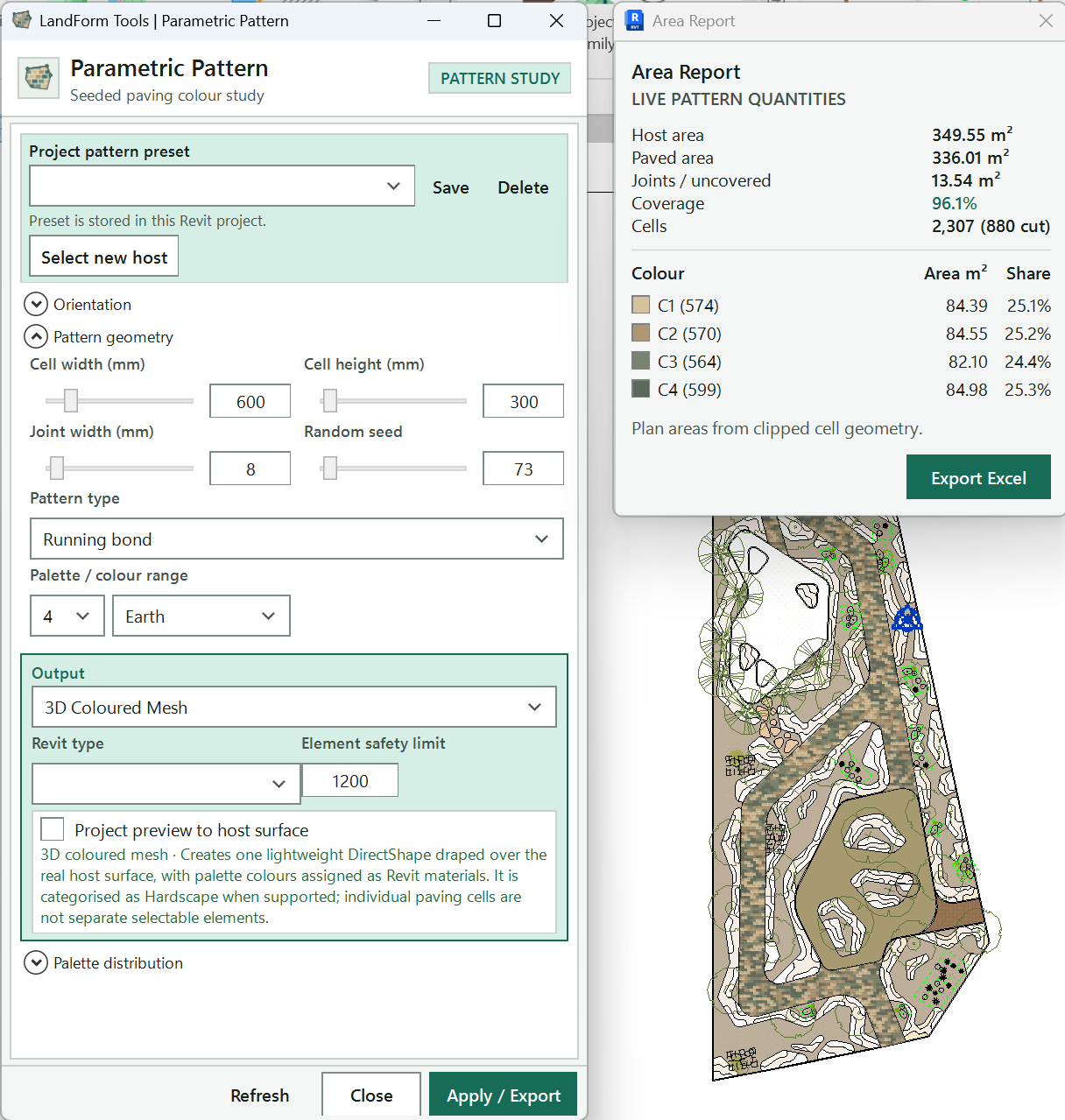
Switch between the host and palette pages, or show them side by side; click the open tab again to hide the options.
Chooses the bond, from stack and running bond to hexagon or the host's own pattern.
The paving unit size and joint; hover a field for a slider.
Reshuffles the colours and stagger without changing anything else.
Turns the whole pattern grid.
Pick a straight edge in the model so the courses run parallel to it.
Slide the grid so a joint lands where you want it.
Redraws the preview over the host now; it also refreshes shortly after each change.
Pick a saved mix to load its settings, or type a new name to save one.
Store every setting in the project, restore the named mix, or remove it.
Creates the chosen output; the label follows Create as on the Materials tab.
Shows the preview state, cell count and progress.
Pick another Floor or Toposolid of the same type and redraw the pattern on it.
Pins the window to the edge of the Revit view.
Open LandForm tab → Patterns panel → Patterns ▾ → Parametric.
Pick the host. Start the tool and click the Floor or Toposolid to pattern. The window opens on the Host tab and draws a first preview over the host.
Choose the bond. Open Pattern type and pick a layout: Stack bond, Running bond, Random stagger, Herringbone, Triangle, Crazy paving, Pentagonal rosette, Hexagon, Octagon and square, Diamond, Basket weave or Selected host pattern. A hint under the list explains how the chosen layout uses the cell size.
Herringbone adds a Herringbone angle field. Selected host pattern repeats the host's own Surface Foreground pattern instead of a generated bond.
Size the units. In the strip under the tabs, set Width (mm), Height (mm) and Joint (mm). Hover a field to get a slider, or type an exact value. Change Seed to reshuffle the colours and stagger without changing anything else.
Orient the pattern. Under Orientation, set Rotation (deg), or click Align to edge and pick a straight edge in the model so the courses run parallel to it. Use Pattern offset X and Pattern offset Y to slide the grid so a joint lands where you want it.
Build the palette. Open the Materials tab. Under Use, choose New Revit materials to define colours yourself, or Existing Revit materials to pick materials already in the project. Set Palette size, pick a Colour range to recolour the swatches, then set each colour's share under Distribution (%) until the total line reads "Total: 100%".
With new materials, click a swatch to change its colour and type a unique material name beside it.
Check the preview. Choose how the host is drawn under Host display in active view, tick Project preview to host surface if the host is shaped, and click Report to see areas and shares per colour.
Choose the output. Under Create as, pick JPEG, Placed PNG, 3D Coloured Mesh, Floors or Toposolids. For Floors and Toposolids, choose the Base type and check Warn above (cells).
Save the mix (optional). Type a name in the Mix name box and click Save to keep every setting in the project for the next host.
Create. Click the action button at the bottom right. Its label follows the output: Export JPEG, Place PNG, Create 3D Mesh, Create Floors or Create Toposolids. Progress shows beside the buttons, and the window stays open for another variation.
What you get depends on Create as. JPEG writes an image file wherever you save it and changes nothing in the model. Placed PNG adds a pinned, foreground image sized to the host in the active plan view ("LF-Parametric Pattern: Place PNG"). 3D Coloured Mesh creates one Hardscape DirectShape per colour, draped over the real host surface, using the palette's Revit materials and grouped in a pinned assembly ("LF-Parametric Pattern: Create 3D Coloured Mesh"); LandForm also loads the LF-PLNT-Pattern Tag family so you can tag the assembly with its material areas and shares. Floors or Toposolids creates one selectable element per paving unit, each using a type named after its colour material ("LF-Parametric Pattern: Bake Cells"). Created output carries pattern parameters such as LF_Pattern Layout, LF_Pattern Area and LF_Pattern Coverage %, so you can schedule it. Each create is a normal Revit undo step.
| Create as | What it makes | Where it goes |
|---|---|---|
| JPEG | A flat image of the pattern | A file you choose; nothing in the model |
| Placed PNG | A pinned foreground image using material shading colours (no textures) | The active plan view, at the host location |
| 3D Coloured Mesh | One Hardscape DirectShape per colour, draped over the host, grouped in an assembly | The model; optional material schedule |
| Floors | One Floor per paving unit, one type per colour | The model, on the host's level |
| Toposolids | One Toposolid per paving unit, one type per colour | The model, on the host's level |
Snaps the window to the edge of the active Revit view and keeps it there while Revit moves or resizes; the button then reads Detach. Drag the window away to float it again.
Shown while the window is snapped. Moves it to the other side of the view; the arrow points to the side it will snap to.
Shows the Host page: saved mixes, Select new host, pattern type and orientation. Click it again while it is the only page open to hide the options and see the preview unobstructed.
Dissolving Pattern only; this tab is removed from the Parametric Pattern window.
Shows the Materials page: palette, distribution, output and live preview settings.
Shows every page side by side and widens the window to fit, which is handy on a second screen. Click again to hide the options.
Paving unit width in millimetres (default 600). Always editable; Pentagonal rosette and Selected host pattern set their own unit, as the hint under Pattern type explains.
Appears when you hover the Width field; drag between 100 and 3000 mm and the preview follows.
Paving unit height in millimetres (default 300).
Appears when you hover the Height field; drag between 100 and 3000 mm.
Joint width between units in millimetres (default 8). Joints count as uncovered area in the report.
Appears when you hover the Joint field; drag between 0 and 100 mm.
Random seed for stagger, density and colour sampling. The same seed always gives the same pattern; change it to reshuffle.
Appears when you hover the Seed field; drag between 0 and 999.
Mix name. Pick a saved mix to load all its settings, or type a new name and click Save. Until you type your own, the name follows the pattern, for example PATT-Running Bond-600x300.
Saves every setting under the name in the box, or updates the mix of that name: materials, colours, shares, sizes, rotation, output, base type and preview options. The host is not saved.
Restores all settings from the named saved mix, discarding current edits.
Deletes the named saved mix from the project.
Returns to Revit so you can pick another Floor or Toposolid with the same type name, then redraws the pattern on it with the current settings.
Chooses the layout: Stack bond, Running bond, Random stagger, Herringbone, Triangle, Crazy paving, Pentagonal rosette, Hexagon, Octagon and square, Diamond, Basket weave or Selected host pattern (the host's own Surface Foreground pattern).
Shown for Herringbone only. Angle of the herringbone in degrees (default 45).
Appears when you hover the field; drag between 0 and 90° in 5° steps.
Turns the whole pattern grid, in degrees.
Appears when you hover the Rotation field; drag between -180 and 180° in 5° steps.
Slides the grid along its own row direction, in millimetres, so a unit edge or joint lines up with the host edge.
Appears when you hover the field; drag between -50,000 and 50,000 mm.
Slides the grid along its own column direction, in millimetres.
Appears when you hover the field; drag between -50,000 and 50,000 mm.
Returns to Revit so you can pick a straight edge; the pattern rotation is set to match it.
Dissolving Pattern only. Hidden in Parametric Pattern.
Dissolving Pattern only. Hidden in Parametric Pattern.
Dissolving Pattern only. Hidden in Parametric Pattern.
Dissolving Pattern only; always hidden. It holds the influence choice made with the three influence buttons.
Dissolving Pattern only. Hidden in Parametric Pattern.
Dissolving Pattern only. Hidden in Parametric Pattern.
Dissolving Pattern only. Hidden in Parametric Pattern.
Dissolving Pattern only. Hidden in Parametric Pattern.
Dissolving Pattern only. Hidden in Parametric Pattern.
Dissolving Pattern only. Hidden in Parametric Pattern.
Dissolving Pattern only. Hidden in Parametric Pattern.
Dissolving Pattern only. Hidden in Parametric Pattern.
Dissolving Pattern only. Hidden in Parametric Pattern.
Dissolving Pattern only. Hidden in Parametric Pattern.
Dissolving Pattern only. Hidden in Parametric Pattern.
Dissolving Pattern only. Hidden in Parametric Pattern.
Dissolving Pattern only. Hidden in Parametric Pattern.
Dissolving Pattern only. Hidden in Parametric Pattern.
Dissolving Pattern only. Hidden in Parametric Pattern.
Dissolving Pattern only. Hidden in Parametric Pattern.
Dissolving Pattern only. Hidden in Parametric Pattern.
Dissolving Pattern only. Hidden in Parametric Pattern.
Dissolving Pattern only. Hidden in Parametric Pattern.
Dissolving Pattern only. Hidden in Parametric Pattern.
Dissolving Pattern only. Hidden in Parametric Pattern.
Dissolving Pattern only. Hidden in Parametric Pattern.
Dissolving Pattern only. Hidden in Parametric Pattern.
Dissolving Pattern only. Hidden in Parametric Pattern.
Dissolving Pattern only. Hidden in Parametric Pattern.
Dissolving Pattern only. Hidden in Parametric Pattern.
Dissolving Pattern only. Hidden in Parametric Pattern.
Dissolving Pattern only. Hidden in Parametric Pattern.
Dissolving Pattern only. Hidden in Parametric Pattern.
Dissolving Pattern only. Hidden in Parametric Pattern.
Dissolving Pattern only. Hidden in Parametric Pattern.
Dissolving Pattern only. Hidden in Parametric Pattern.
Dissolving Pattern only. Hidden in Parametric Pattern.
Dissolving Pattern only. Hidden in Parametric Pattern.
Dissolving Pattern only. Hidden in Parametric Pattern.
Dissolving Pattern only. Hidden in Parametric Pattern.
Use: New Revit materials lets you set each colour and name and creates those materials on output; Existing Revit materials lets you pick a project material for each slot and uses its shading colour in the preview.
Palette size: how many colours the pattern uses (2 to 10 here). Use Add material for more. Reducing the size keeps the hidden entries for reuse.
Recolours the new-material swatches from a preset range: Earth, Teal, Greens, Greys, Blues or Bright. Custom keeps your own colours. Hidden when you use existing materials.
Adds another palette entry at 0%. Existing colours, names and shares are kept; raise the new entry's share to use it.
Create as: JPEG, Placed PNG, 3D Coloured Mesh, Floors or Toposolids. Hover an entry in the list for a description. The action button's label changes to match.
Base type (thickness and layers), shown for Floors and Toposolids. Each colour gets its own named copy of this type with the colour's material on the top layer; thickness and other layers are kept and the base type is not changed.
Warn above (cells), shown for Floors and Toposolids (default 1200). Above this count, Create asks first: Yes creates the whole pattern, No cancels. It is a warning, not a cap.
Shown for 3D Coloured Mesh. Creates one native Revit schedule for this pattern and its ordered palette; matching meshes created later appear in it automatically.
Opens or closes the Area Report beside this window.
How the host is drawn in the active view while you work: White surface, hide native patterns (recommended); Hide all host patterns; or Keep current host graphics. It is a view-only override; the host material and other views are unchanged.
Keeps the host display override in this view after an image, mesh or element output is created, so the new pattern stays clear. Off, the original host graphics return when the tool closes.
Drapes the on-screen preview over a shaped Floor or Toposolid instead of drawing it flat. Exports and created output are not affected.
Redraws the preview now. It also refreshes on its own shortly after you change a setting.
Closes the tool, clears the preview and restores any temporary host display. Output you already created stays.
Creates the chosen output. The label follows Create as: Export JPEG, Place PNG, Create 3D Mesh, Create Floors or Create Toposolids. Disabled until the distribution totals 100% and every material is named or chosen.
Expands or collapses the live report: host area, paved area, uncovered remainder, coverage, cell count, and the area and share of every colour. Areas come from the clipped unit geometry.
Saves the current report as an Excel workbook (.xlsx) wherever you choose.

Patterns · Patterns · Dissolving
Dissolving Pattern is the paving tool for transitions: a plaza whose setts break up into planting, a path edge that fades into gravel, rings of pavers around a tree. You choose what drives the effect, set how far it reaches and how small, sparse or recoloured the units become at the far end, and watch the result live over the host. It shares its pattern types, palette and outputs with Parametric Pattern, so the finished study can become an image, a 3D coloured mesh or one Floor or Toposolid per paving unit.
LandForm tab→Patterns panel→Patterns ▾→Dissolving
Button tooltip: “Generate paving patterns from a radial point, a path-free circular array, or multiple live paths.”Dissolving Pattern walkthrough. Until it is published, the steps and the annotated window below walk through the same workflow.
Numbers on the screenshot match the legend. Hover a number or a legend row to highlight the other.
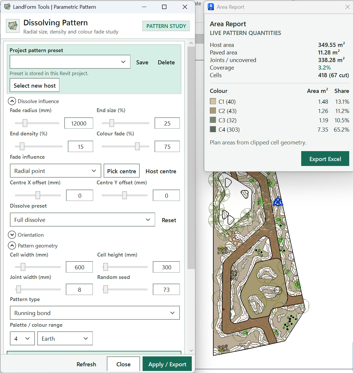
The window opens snapped beside the Revit view; Detach floats it and the arrow moves it to the other side.
Switches between the pages; All shows every page side by side.
Radial point dissolves around a centre, Selected path follows picked lines, Perfect circle lays the paving in concentric rings.
Click the influence centre in the view (Esc keeps the last one), or put it back in the middle of the host.
Fine-tunes the centre's distance from the host centre.
Picks a dissolve preset; Reset restores the default dissolve, influence and colour settings.
How far the effect reaches from the influence.
How small and how sparse the units are at the fade radius, and the smallest trimmed piece to keep.
Colour mode, Colour fade (%), Fade target colour and Fade direction set how units change colour with distance.
Paving unit size, joint width and the random seed that reshuffles which units drop out.
Reports the preview state, cell count and time, with a progress bar.
Redraws the preview now; it also refreshes shortly after each change.
Creates the chosen output; the label follows Create as on the Materials tab.
Closes the tool and clears the preview and grips; output already created stays.
Open LandForm tab → Patterns panel → Patterns ▾ → Dissolving.
Pick the host. Start the tool and click the Floor or Toposolid. The window opens snapped beside the Revit view on the Dissolve tab, and a first preview is drawn over the host.
Choose the influence. Under Influence source, click Radial point for a dissolve around a centre, Perfect circle for paving set in concentric rings, or Selected path for a dissolve that follows lines.
For a centre, click Pick centre and click in the view; keep clicking to compare positions, then press Esc to keep the last one. Host centre puts it back in the middle of the host, and Centre X offset and Centre Y offset fine-tune it. For paths, click Pick paths, select one or more lines and click Finish. The status line confirms how many paths and curves are linked.
Arrange the units along the guide. With Selected path or Perfect circle, choose a Path arrangement. Influence only keeps a straight grid, Follow tangent turns each unit to the guide, Array along curve lays rows of units along it, and Follow curve + auto-cut bends the units to the curve and trims them where rows collide or meet the host edge. For rows along a path, set Pattern start offset and Row offset to place the first unit.
Shape the dissolve. Pick a Dissolve preset, then set Fade radius (how far the effect reaches), End size (%) and End density (%) (how small and how sparse the units are at that distance). Min cut size (%) drops slivers left by trimming.
For a centre-based dissolve you can also drag the grips in the view: the centre dot moves the influence (it snaps to the host centre), the cyan square changes the radius and the amber grip rotates the pattern. With paths, each path has its own radius and start grips. Release to refresh; Esc cancels a drag.
Set the colour transition. Under Colour mode, Fade blend swaps a growing share of units to the Fade target colour, up to the Colour fade (%) you set, in the Fade direction you choose. Divide into parts paints hard-edged colour bands instead, by Number of parts or Band distance.
Pick the pattern and unit size. On the Host tab, choose the Pattern type and Orientation, and set Width (mm), Height (mm), Joint (mm) and Seed in the strip under the tabs.
Build the palette and choose the output. On the Materials tab, set the colours or project materials and their Distribution (%), then choose Create as: JPEG, Placed PNG, 3D Coloured Mesh, Floors or Toposolids.
Create. Click the action button at the bottom right; its label follows the output (for example Create 3D Mesh). The window stays open, so you can save the mix and try another variation.
The output is the same as in Parametric Pattern, with the dissolve applied: units shrink, drop out and change colour exactly as the preview showed, and cut pieces are trimmed to the host. JPEG only writes a file. Placed PNG adds a pinned foreground image in the active plan view. 3D Coloured Mesh adds pinned, schedulable Hardscape geometry draped over the host, one shape per colour, grouped in an assembly. Floors and Toposolids create one element per unit with a type for each colour. Created output carries pattern parameters such as LF_Pattern Layout and LF_Pattern Coverage %, and each create is one undo step whose name starts "LF-Parametric Pattern:". The picked guide lines are only references and are never part of the output.
| Influence source | Arrangement choices | What the arrangement does |
|---|---|---|
| Radial point | None | The grid stays straight; size, density and colour change with distance from the centre. |
| Selected path | Influence only | The grid stays straight; the dissolve is measured from the nearest picked line. |
| Selected path | Follow tangent | Each unit is turned to follow the nearest line. |
| Selected path | Array along curve | Whole units are laid in offset rows along each line. |
| Selected path | Follow curve + auto-cut | Units bend with the line, rows close evenly, and collisions and the host edge are trimmed. |
| Perfect circle | Circular influence, Follow circle tangent, Radial array | Units stay square to the grid, turn to the ring, or are laid in true concentric rings (the default). |
The Dissolving Pattern window opens snapped to the edge of the active Revit view and follows it, and the button reads Detach. Click it to float the window, or Snap to pin it again.
Shown while the window is snapped. Moves it to the other side of the view; the arrow points to the side it will snap to.
Shows the Host page: saved mixes, Select new host, pattern type and orientation. Click it again while it is the only page open to hide the options for an unobstructed preview.
Shows the Dissolve page: influence source, dissolve settings and colour transition. The window opens on this tab.
Shows the Materials page: palette, distribution, output and live preview settings.
Shows every page side by side and widens the window to fit, which is handy on a second screen. Click again to hide the options.
Paving unit width in millimetres (default 600). When units are arrayed along a curve or ring it sets the spacing along it.
Appears when you hover the Width field; drag between 100 and 3000 mm.
Paving unit height in millimetres (default 300). When units are arrayed along a curve or ring it sets the row depth.
Appears when you hover the Height field; drag between 100 and 3000 mm.
Joint width between units in millimetres (default 8).
Appears when you hover the Joint field; drag between 0 and 100 mm.
Random seed for stagger, density and colour sampling. The same seed always gives the same pattern; change it to reshuffle which units drop out and which change colour.
Appears when you hover the Seed field; drag between 0 and 999.
Mix name. Pick a saved mix to load all its settings, including the dissolve, or type a new name and click Save. Until you type your own, the name follows the pattern, for example PATT-Running Bond-600x300.
Saves every setting under the name in the box, or updates the mix of that name: palette, sizes, rotation, dissolve and colour settings, output and preview options. The host and picked paths are not saved.
Restores all settings from the named saved mix, discarding current edits.
Deletes the named saved mix from the project.
Returns to Revit so you can pick another Floor or Toposolid with the same type name, then redraws the pattern on it with the current settings.
Chooses the layout: Stack bond, Running bond, Random stagger, Herringbone, Triangle, Crazy paving, Pentagonal rosette, Hexagon, Octagon and square, Diamond, Basket weave or Selected host pattern. Hidden while units are arrayed along a curve.
Shown for Herringbone only. Angle of the herringbone in degrees (default 45).
Appears when you hover the field; drag between 0 and 90° in 5° steps.
Turns the pattern grid, in degrees. On a Perfect circle it sets where the rings start. Hidden while units are arrayed along a picked path.
Appears when you hover the Rotation field; drag between -180 and 180° in 5° steps. The amber grip in the view does the same.
Slides the grid along its own row direction, in millimetres. The influence centre does not move with it.
Appears when you hover the field; drag between -50,000 and 50,000 mm.
Slides the grid along its own column direction, in millimetres.
Appears when you hover the field; drag between -50,000 and 50,000 mm.
Returns to Revit so you can pick a straight edge; the pattern rotation is set to match it. With a picked path and a straight grid, the anchor unit stays in place while the pattern turns.
Radial point: the dissolve radiates from a centre you pick or offset from the host centre.
Selected path: the dissolve follows picked model or detail lines, measured as the shortest plan distance to the nearest line; units can array along them.
Perfect circle: units are arranged in rings around the influence centre, with no lines needed.
Always hidden; it holds the choice made with the three influence buttons above.
Returns to Revit so you can click the influence centre. Keep clicking to try other positions; Esc keeps the last one. Shown for Radial point and Perfect circle.
Puts the influence centre back in the middle of the host by setting both centre offsets to 0.
Select one or more model or detail lines, then click Finish. Connected segments form one guide; separate selections stay independent, and all of them stay linked to the preview.
Centre X offset: distance of the influence centre from the host centre along X, in millimetres.
Appears when you hover the field; drag between -50,000 and 50,000 mm, or drag the centre dot in the view.
Centre Y offset: distance of the influence centre from the host centre along Y, in millimetres.
Appears when you hover the field; drag between -50,000 and 50,000 mm.
Shown for Selected path and Perfect circle. For paths: Influence only, Follow tangent, Array along curve, or Follow curve + auto-cut, which bends units along the paths, fits closed rows evenly and trims collisions and the host edge. For a circle: Circular influence, Follow circle tangent or Radial array.
Pattern start offset, shown when units are arrayed along picked paths. 0 starts a full unit exactly at the path start; positive values slide it forward, negative back. On closed loops it moves where the ring of units begins.
Appears when you hover the field; drag between -50,000 and 50,000 mm, or drag the amber grip on the path.
Row offset: slides the rows across the path. 0 puts the first row's edge on the path; positive values move rows to the left of the path direction, negative to the right.
Appears when you hover the field; drag between -50,000 and 50,000 mm, or drag the amber corner grip to set start and row offsets together.
Restores the default dissolve, influence and colour settings: Radial point at the host centre, Full dissolve, the starting radius, 25% end size, 15% end density and 75% colour fade. The palette, pattern type and output are kept.
Full dissolve shrinks and thins units (25% size, 15% density at the radius). Colour fade only keeps every unit full size and fades colour. Fixed size along guide switches to Selected path with Array along curve and lays whole units along the picked path with no fade.
Fade radius in millimetres: the distance over which units reach the end size and density. It starts at half the shorter side of the host's plan bounding box. With paths it reads All path radii and sets every path at once.
Appears when you hover the field; drag between 1,000 and 50,000 mm, or drag the cyan square grip in the view.
End size (%): unit size at the fade radius as a share of the full size. Units shrink steadily from 100% at the influence.
Appears when you hover the field; drag between 5 and 100%.
End density (%): share of units kept at the fade radius. Units drop out at random, more of them the farther they are from the influence.
Appears when you hover the field; drag between 0 and 100%.
Min cut size (%): smallest trimmed piece to keep, as a share of its unit at its faded size. Pieces cut by the host edge, a guide end or a neighbouring row that fall below it are left out. 0 keeps every fragment.
Appears when you hover the field; drag between 0 and 100%.
Shown when units are arrayed along picked paths. On (default), each row runs past both guide ends so the ends are fully paved and the overhang is cut. Off, the rows stop at the guide start and end.
Fade blend mixes colours randomly toward the fade target across the influence distance. Divide into parts splits the distance from the influence into hard-edged bands, one palette colour per band, with no fading.
Division method for Divide into parts. Equal parts splits the whole surface extent into the chosen number of bands; By distance makes every band a fixed width and repeats the palette outward.
Number of parts for Equal parts, from 2 to 12. Colours repeat when there are more parts than palette colours.
Appears when you hover the field; drag between 2 and 12.
Band distance in millimetres for By distance: the width of every colour band.
Appears when you hover the field; drag between 100 and 50,000 mm.
Start offset in millimetres: the distance from the influence before the first band begins.
Appears when you hover the field; drag between 0 and 50,000 mm.
Colour fade (%): the largest share of units that change to the fade target colour, reached at the far end of the fade. 0 turns the colour fade off.
Appears when you hover the field; drag between 0 and 100%.
Fade target colour: the palette colour (C1, C2 and so on) that units change to. It defaults to the last colour.
Fade blend: Away from influence puts the target colour toward the outside; At influence concentrates it on the centre or path. With Divide into parts the label becomes First colour (C1): C1 at influence or C1 at outer edge.
Shown for Selected path with Fade blend. Sets the target colour to 0% in the base mix so it appears only in the path fade, and shares the rest toward the lighter colours.
Use: New Revit materials lets you set each colour and name and creates those materials on output; Existing Revit materials lets you pick a project material for each slot and uses its shading colour in the preview.
Palette size: how many colours the pattern uses (2 to 10 here). Use Add material for more. Reducing the size keeps the hidden entries for reuse.
Recolours the new-material swatches from a preset range: Earth, Teal, Greens, Greys, Blues or Bright. Custom keeps your own colours. Hidden when you use existing materials.
Adds another palette entry at 0%. Existing colours, names and shares are kept; raise the new entry's share to use it.
Create as: JPEG, Placed PNG, 3D Coloured Mesh, Floors or Toposolids. Hover an entry in the list for a description. The action button's label changes to match.
Base type (thickness and layers), shown for Floors and Toposolids. Each colour gets its own named copy of this type with the colour's material on the top layer; the base type is not changed.
Warn above (cells), shown for Floors and Toposolids (default 1200). Above this count, Create asks first: Yes creates the whole pattern, No cancels.
Shown for 3D Coloured Mesh. Creates one native Revit schedule for this pattern and its ordered palette; matching meshes created later appear in it automatically.
Opens or closes the Area Report beside this window.
How the host is drawn in the active view while you work: White surface, hide native patterns (recommended); Hide all host patterns; or Keep current host graphics. It is a view-only override; the host material and other views are unchanged.
Keeps the host display override in this view after an image, mesh or element output is created. Off, the original host graphics return when the tool closes.
Drapes the on-screen preview over a shaped Floor or Toposolid instead of drawing it flat. Exports and created output are not affected.
Redraws the preview now. It also refreshes on its own shortly after you change a setting.
Closes the tool, clears the preview and grips and restores any temporary host display. Output you already created stays.
Creates the chosen output. The label follows Create as: Export JPEG, Place PNG, Create 3D Mesh, Create Floors or Create Toposolids. Disabled until the distribution totals 100% and every material is named or chosen.
Expands or collapses the live report: host area, paved area, uncovered remainder, coverage, cell count, and the area and share of every colour after the dissolve.
Saves the current report as an Excel workbook (.xlsx) wherever you choose.
LandForm ribbon panel
Reshape, split, align, convert and project elements onto surfaces.

Modify · Drape
Drape is how you make paving, kerb slabs, path floors or a thin toposolid sit on the terrain instead of floating at a level. You set how the two surfaces should meet, press Run, click the source surface to read levels from and then the floors or toposolids that should follow it. LandForm projects every target point onto the source and writes the result as native shape points, so Revit's own Modify Sub Elements tools still work afterwards.
The source can be a floor, toposolid, legacy topography, a generic model or other family, a model line, or a CAD link or import, and it may sit inside a Revit link. Targets are floors and toposolids in the current model that Revit allows you to shape-edit.
LandForm tab→Modify panel→Drape
Button tooltip: “Drape editable surfaces to another terrain reference.”Drape walkthrough. Until it is published, the steps and the annotated window below walk through the same workflow.
Numbers on the screenshot match the legend. Hover a number or a legend row to highlight the other.

Which source face drives which target face, source first; here Top to Top.
Where the shape points come from: Base Pts (default), Boundary, Bnd Spaced, Bnd+Inside or Split, shown here.
Lifts (positive) or lowers (negative) the result after projection, in metres.
With Auto on, the snap reach is measured each run; untick it to type a Snap distance yourself.
Adds points along straight target edges at this spacing, 0.5 m by default.
Adds points along curved target edges at this spacing.
Adds dense face samples when the source points are too sparse; Base Pts and Split only.
Removes the target's existing shape points first; Split switches it on, so it is greyed here.
Saves the settings, then asks you to pick the source and the target surfaces.
Tells you the next step, then shows progress and "Drape complete" with the counts.
Removes shape editing from the selected floors and toposolids, or from every eligible visible surface, after a confirmation.
Open LandForm tab → Modify panel → Drape.
Set the alignment. Open Align and choose how the faces meet. Each entry names the source face first and the target face second: Top to Top keeps the target top on the source top, Top to Bottom sets the target underside on the source top, Bottom to Top sets the target top on the source underside, and Bottom to Bottom aligns both undersides. Element thicknesses are taken into account automatically.
Choose the point source. Open Points. Base Pts (the default) copies the source's own interior points onto the target, which gives a light, exact result. Boundary uses only the target outline and is fastest. Bnd Spaced places boundary points by distance only, Bnd+Inside adds the source's interior points to those, and Split adds split-line constraints for a tighter triangulation.
Base Pts, Bnd+Inside and Split switch Clear on automatically so old shape points cannot remain.
Set the offset and snap reach. Type an Offset in metres to lift (positive) or lower (negative) the result after projection, or tick the Auto box beside it to take the offset from each target's own type thickness instead: every picked target is lifted by its thickness from the chosen alignment, so with Top to Top a planting bed or paving surface stands on the source with its underside on it rather than flush with it, and targets of different types each rise by their own thickness in one run. The Offset box hides while its Auto is on. Leave the Snap Auto on so the Snap distance is measured each run from how far the target boundaries reach beyond the source (capped at 2 m and never less than the target thickness), or untick it and type a Snap distance yourself.
Target points that fall outside the source are snapped to the nearest point on the source boundary within this reach; points beyond it are dropped.
Add boundary and face points (optional). Tick Line or Curve and set a spacing in metres to add points along straight or curved edges of the target (0.5 m by default). Tick Faces to add dense face samples when the source points are too sparse; it is available in Base Pts and Split modes only.
Tick Clear to remove the target's existing shape points before the new ones are written.
Run and pick the source. Press Run. Revit asks for the source element to read elevations from: click the floor, toposolid, topography, generic model, model line or CAD link, in the current model or in a link.
As you move the cursor, the status line names the surface Revit would take ("Under the cursor: Toposolids : LF-Ground · about 42 × 9 m") and its footprint is outlined in the view, so where surfaces overlap (paving or a planting bed lying on the terrain, for example) you can see which one is live before you click; Tab cycles the overlapping ones. If you click the wrong one anyway, LandForm lists every surface under the point top-down with each one's type, height at the click, footprint size and element Id, marks the one Revit selected, and asks which is the source; Pick again returns to the view. A click on a model line or a CAD import is taken as meant.
Pick the targets. Click the floors or toposolids to drape and press Finish. Only elements that accept shape editing can be selected.
Answer the flat-source prompt if it appears. When the source is flat, LandForm offers Align by Height Offset From Level (fast), which shifts each target's Height Offset From Level instead of adding points, or Normal drape for the full projection.
Watch the status line. The progress bar runs while points are projected and a Cancel button appears; pressing it rolls back the whole run. When it finishes the status line reads "Drape complete" with the number of successful and failed targets, and why each failed target failed: a failed target keeps its old position, which is the usual reason a surface floats above the terrain after a run. In Top to Bottom and Bottom to Bottom it also names targets whose type has a variable-thickness layer, because such a target keeps a flat underside whatever its top does and cannot sit on a sloping base; untick Variable in the type's Structure.
Each target now carries native shape points that follow the source at the alignment and offset you chose, so its top (or underside) hugs the terrain. The points are ordinary Revit sub-elements: Modify Sub Elements, Point Grip and Relax Surface can edit them further. A normal run is one undo step named "LF-Drape: Drape to Surface"; the flat-source shortcut is "LF-Drape: Drape to Flat Elevation". Your settings are saved and restored the next time you open Drape.
Chooses which face of the source drives which face of the target: Top to Top, Top to Bottom, Bottom to Top or Bottom to Bottom (source face first). Element thicknesses are added or subtracted automatically.
Boundary uses the target outline only (fastest). Bnd Spaced adds boundary points by distance. Bnd+Inside adds spaced boundary points plus the source's interior points. Base Pts copies the source's interior points (default). Split adds split-line constraints for tighter triangulation.
Vertical offset in metres applied after projection: positive lifts, negative lowers. Hidden while the Offset Auto box is on.
Takes the offset from each target's own type thickness: every target is lifted by its thickness from the chosen alignment, so Top to Top stands it on the source instead of flush with it. Hides the manual Offset box.
How far a target point that falls outside the source may be snapped to the nearest point on the source boundary, in metres. Points beyond this reach are dropped. Larger values may reduce accuracy. Hidden while the Snap Auto box is on.
Measures the snap distance each run from how far the target boundaries sit outside the source (capped at 2 m, never less than the target thickness) and hides the manual Snap box.
Removes the target's existing shape points before the projected points are written. Switched on automatically for Base Pts, Bnd+Inside and Split.
Adds points along straight boundary segments at the Line spacing. Locked on in Bnd Spaced and Bnd+Inside.
Distance in metres between generated points along straight segments (0.5 by default).
Adds points along curved boundary segments at the Curve spacing. Locked on in Bnd Spaced and Bnd+Inside.
Distance in metres between generated points along curves (0.5 by default).
Adds dense face samples on top of the base points when they are too sparse. Available in Base Pts and Split modes only.
Development diagnostic, hidden in the released toolbar: draws the snap zone and dropped points as a temporary Generic Model after the run.
Removes shape editing from the selected floors and toposolids, or from all eligible surfaces visible in the view when nothing is selected, after a Yes/No confirmation.
Saves the settings, then asks you to pick the source and the target surfaces and drapes them.
Shown while a run is in progress. Stops the run and rolls back every change it made.

Modify · Convert
The Convert button is for the moment a surface was modelled as the wrong class: a landscape area drawn as a floor that now needs toposolid behaviour, or a toposolid that should really be a paving floor. Instead of redrawing the sketch and re-entering every point, you select the surfaces, confirm once, and LandForm rebuilds each one as the opposite class on the same level and removes the original.
Because Revit cannot change an element's class in place, the result is a new element with a new Element Id. Anything that pointed at the old element, such as tags, dimensions, hosted elements or constraints, is not transferred; the confirmation dialog reminds you of this before anything changes.
LandForm tab→Modify panel→Convert
Button tooltip: “Convert floors to toposolids, or toposolids to floors.”Floor / Toposolid Converter walkthrough. Until it is published, the steps and the annotated window below walk through the same workflow.
Numbers on the screenshot match the legend. Hover a number or a legend row to highlight the other.
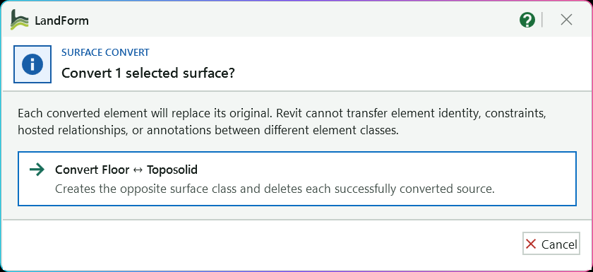
States how many selected surfaces will be converted.
Each new element replaces its original; tags, dimensions, hosted elements and constraints do not carry across.
Goes ahead: floors become toposolids and toposolids become floors in the same run.
Each surface is rebuilt on the same level with its outline, openings and shape points, then the original is deleted; a surface that fails is left untouched.
Closes the dialog with nothing changed.
Open LandForm tab → Modify panel → Convert.
Select the surfaces. Select floors and toposolids in the view and press Convert, or press Convert first, click the surfaces one by one and press Finish. Foundation slabs and other element kinds are skipped.
Confirm the replacement. The Surface Convert dialog states how many surfaces will be converted and that each new element replaces its original. Choose Convert Floor ↔ Toposolid to go ahead, or close the dialog to cancel with nothing changed.
Let LandForm rebuild each surface. For every selected element it reads the sketch (outer boundary and openings), the level, the height offset and the shape points, finds or creates a matching type of the opposite class, creates the new element, copies its parameters, re-applies the shape points and deletes the original.
Floors become toposolids and toposolids become floors in the same run; mixed selections are fine.
Read the report. A report dialog says "Conversion complete", "Conversion partially complete" or "Conversion could not be completed", lists how many floors and toposolids were converted, and notes any surfaces that failed. Open the details for the new element ids, any optional values that could not be copied, and Revit's own message.
Review the new surfaces. They are left selected when the dialog closes, so you can check them in the Properties palette or in a 3D view straight away.
Each converted surface is replaced by a new element of the opposite class on the same level, with the same outline and openings, the same Height Offset From Level value, and its shape points re-applied so the surface keeps its grading. The type is a floor or toposolid type with the same name as the original type; when LandForm has to create it, it copies the compound structure (layers and materials) and the type parameters from the source type. Workset, Comments, Mark, phases, pinned state and shared or project parameters bound to both categories are copied too. LandForm pattern overlays and parametric pattern modules hosted on the original are rebuilt onto the new element. The whole run is one undo step, and a surface that fails is rolled back on its own without affecting the others.
No separate LandForm window. This command runs directly from Revit selection and prompts; follow the workflow above and the messages shown beside the cursor or on Revit's status bar.

Modify · Surface · Split
Split saves you from copying a surface and editing two sketches by hand when a lawn, a paved area and a planting bed need to become separate elements with their own type, material or phase. You pick the surface, choose how to draw the splitter (a line and arc path, a rectangle, a polygon, a circle, an arc, existing lines, or the edges of another element such as a kerb), and LandForm rewrites the boundary sketches for you. The original element keeps one region and each other region becomes a copy of it, so type, parameters and shape stay the same on every piece.
With Trim on, only what you want is kept: after the splitter, click the part to remove and it is gone, the way Trim works in CAD. One splitter can trim every floor and toposolid it crosses, so a row of paving strips that runs onto a kerb is cleaned up in one pass instead of an Edit Boundary on each.
With Offset boundary there is nothing to draw: the surface's own edge, moved out or in by a distance, is the splitter. Outside, the band around the surface becomes a new surface of the same type (a mowing strip around a lawn, a kerb band around paving); inside, the band along the edge is split off the surface itself.
LandForm tab→Modify panel→Surface ▾→Split
Button tooltip: “Divide or trim a floor or toposolid along a splitter path.”Split walkthrough. Until it is published, the steps and the annotated window below walk through the same workflow.
Numbers on the screenshot match the legend. Hover a number or a legend row to highlight the other.

Chooses how the splitter is drawn: a line and arc path, rectangle, polygon, circle, three-point arc, existing lines, picked edges or the offset boundary.
Number of sides, 3 to 24; only active for Polygon.
Removes the closed shape as an opening instead of making it a separate surface.
Starts drawing the splitter on the surface; the split or hole is applied as soon as the drawing is finished.
Tells you the next step, then reports how many surface regions were created.
Open LandForm tab → Modify panel → Surface ▾ → Split.
Pick the surface. Start the tool and click the floor or toposolid you want to divide. If a supported surface is already selected, the toolbar opens straight away without asking.
Choose a drawing method. Open Draw and pick the shape of the splitter. For Polygon, type the number of Sides. For Offset boundary, type the Offset distance in metres and choose Outside or Inside.
Decide between a split, a hole and a trim. Leave Hole and Trim off to keep every region as its own surface. Turn Hole on when you want a closed shape removed from the surface as an opening. Turn Trim on when you want to delete the part on one side of the splitter. Hole and Trim cannot both be on, and neither applies to a band outside the surface.
Press Draw and draw the splitter. Click points on the surface. The preview line follows the cursor, and the endpoint, midpoint, intersection, nearest and alignment snaps help you land on existing geometry.
Line / Arc path: click for straight segments; hold Shift while you click an endpoint to make that segment an arc, then click a point on the arc. Press Esc to finish. Rectangle: two opposite corners. Polygon and Circle: the centre, then a radius point. Three-point arc: start, end, then a point on the arc. Pick existing lines: click one line of the chain; every connected line of the same kind (model or detail) in the view is collected for you. Pick edges: click the edges to cut along, one at a time, then press Esc. Edges that meet end to end join into one line, and edges that do not meet each make their own cut. Click a picked edge again to drop it. Offset boundary: the button reads Offset and there is nothing to click. Every edge of the surface, holes included, is moved by the distance: Outside grows the surface, Inside shrinks it. Lines stay lines and arcs stay arcs; only where an edge would fold back on itself (an arm narrower than twice the distance, a gap that closes) is it redrawn as a polyline, and the status line says so.
Let LandForm apply it. When the splitter is complete, LandForm checks that it really divides or encloses part of the surface and applies the change. The status line reports how many surface regions were created.
With Trim on, nothing changes yet: click each part to remove instead. In a plan view the part under the cursor turns red before you click. You can click parts of the surface you started with or of any other floor or toposolid the splitter crosses. Each click is applied straight away. Press Esc when you are done. With Offset boundary, Outside, the surface is not touched: the band gained around it (and into each hole wider than twice the distance) is created as a new surface, a copy of this one with the band as its boundary. Inside, the band along the edge is split off like any other region: the surface keeps the inside and the band becomes a copy. With Hole on, the inside becomes an opening instead and the surface keeps the band; tick Keep inside to keep the inside as well, as a surface of its own sitting in the opening. Trim works as usual.
Split again or close. The toolbar stays open, so you can choose another method and press Draw again on the same surface. Press Close when you are done.
The original floor or toposolid now holds one of the regions, and every other region is a copy of it with the same type, parameters and level. With Trim, the part you clicked is deleted and the element keeps the rest, so its id, tags and schedule entries stay with it. If the splitter crosses a surface more than once, the pieces left after a trim become separate elements, and the original keeps the largest. Along the new edges LandForm adds shape points projected onto the original top surface, so sloped terrain keeps its heights where it was cut; the status line tells you how many points were restored. With Hole on, the surface keeps its outline and gains an opening. With Offset boundary, Outside, the surface is unchanged and a new surface of the same type, level and offset holds the band; on a shaped surface the band's inner edge sits on the surface's top and its outer edge carries those heights across, so a kerb band around sloped paving follows the paving. Each split is one step in Revit's undo list, named "LF-Split Surface" (or "LF-Create Surface Opening" for a hole, "LF-Offset Surface Boundary" for a band outside). Each trim click is a step of its own, named "LF-Trim Surface".
Chooses how the splitter is created: Line / Arc path, Rectangle, Polygon, Circle, Three-point arc, Pick existing lines, Pick edges, or Offset boundary.
Polygon side count from 3 to 24. Only active for the Polygon method.
Distance from the surface boundary in metres. Only active for the Offset boundary method.
Which side of the boundary the band lies on: Outside makes a new surface around this one and leaves it unchanged; Inside splits the band along the edge off this surface.
Subtract the closed drawing as an opening instead of creating a separate inner surface. With Offset boundary, Inside, the part inside the offset becomes the opening and the band is kept.
With Hole on for an inside offset: keep the part inside the opening as a surface of its own instead of removing it. The surface keeps the band with the opening; the inside becomes a copy.
Remove the parts you click instead of keeping every piece. After the splitter, click each part to delete, on this or any other floor or toposolid it crosses; press Esc to finish.
Start drawing or picking the selected splitter in Revit; the split or hole is applied as soon as the drawing is finished, and with Trim on you then click the parts to remove. With Offset boundary the button reads Offset and applies at once.
Closes the Split Surface toolbar and clears the preview.

Modify · Surface · Merge
Merge is the opposite of Split and Explode. Paving laid as strips, a lawn drawn in two halves, planting beds that grew piece by piece or a terrain split for an earlier edit can all be put back together without redrawing a sketch. You select the surfaces and LandForm works out the overall outline in plan, the way a boolean union does, then creates one new floor or toposolid from it with the type, level, offset, comments and shared parameters of the largest surface you selected. The shape points and split lines of every source are carried across so a sloped top stays as it was. Nothing is edited in place: the originals are either deleted or left where they are, as you choose.
LandForm tab→Modify panel→Surface ▾→Merge
Button tooltip: “Combine floors or toposolids into one new element.”Merge walkthrough. Until it is published, the steps and the annotated window below walk through the same workflow.
Open LandForm tab → Modify panel → Surface ▾ → Merge.
Select the surfaces. Select two or more floors, or two or more toposolids, before you start the tool, or start it and click them in the view, then press Finish on the Options Bar. Only floors and toposolids can be picked; one surface alone, or a mix of floors and toposolids, is refused with a message and nothing changes.
Choose what happens to the originals. A LandForm dialog names the surface the new one takes its type, level, offset and parameters from, and offers Merge and delete the originals or Merge and keep the originals. The first choice also counts the elements hosted on the originals, which go with them. Close the dialog to do nothing.
Let LandForm merge them. The overall outline is computed in plan: arcs stay true arcs (an arc cut by another surface comes back as the arc that is left, and two arcs of one circle meeting at a seam become a single arc), corners along the seams are cleaned up so two squares become one rectangle, and hair-thin slivers where two surfaces drew a shared edge slightly differently are healed. A new surface is created from the outline. Where any surface is shaped, or the surfaces sit at different heights, shape editing is turned on and the boundary corners, every source's shape points and their user-drawn split lines are added so the merged top follows the surfaces it came from. Flat surfaces at one height merge into a flat surface with no shape editing. With delete chosen, the originals are then removed.
Read the summary. A LandForm dialog says which surface the new one was modelled on, whether the outline is one piece or several, how much overlap was counted once, how many arcs were kept, and how many shape points, split lines and parameters were carried over. The new surface is left selected.
One new floor or toposolid holds the combined outline, with the type, level, offset and parameters of the largest original. Holes stay holes unless another surface covered them. The originals are gone or still in place, as you chose. If Revit cannot accept the outline with its arcs, the outline is drawn as straight segments instead and the dialog says so. The whole merge is one step in Revit's undo list, named "LF-Merge Surfaces", so Undo brings deleted originals back.
No separate LandForm window. This command runs directly from Revit selection and prompts; follow the workflow above and the messages shown beside the cursor or on Revit's status bar.

Modify · Surface · Opening
Use Opening when a planter, a pool, a building footprint or a tree pit has to be cut out of a paving slab or a terrain toposolid. Instead of editing the boundary sketch by hand, you point at the thing that should make the hole: LandForm can detect visible elements overlapping the surface, follow the outline of another floor or toposolid, trace the loop of an edge you click, use connected lines, or let you draw a rectangle, circle or line and arc loop. An Offset grows or shrinks the cut, so you can leave a clearance gap or an edge strip without redrawing anything.
LandForm tab→Modify panel→Surface ▾→Opening
Button tooltip: “Create an opening in a floor or toposolid.”Opening walkthrough. Until it is published, the steps and the annotated window below walk through the same workflow.
Numbers on the screenshot match the legend. Hover a number or a legend row to highlight the other.

The status line tells you what to click or draw next.
Names the floor or toposolid you picked to cut.
Where the cutter boundary comes from: Auto, Surface, Edge, Lines or Draw.
Grows (positive) or shrinks (negative) the cutter boundary, in metres.
Finds, picks or draws the cutter; the label follows the source.
Shows how many cutter loops were found.
Click cutters in the view to drop them from the list; press Esc when done.
Redraws the cutter boundary at the current offset.
Cuts the previewed boundary out of the target and restores its heights.
Clears the target, cutter and preview and asks you to pick the target again.
Open LandForm tab → Modify panel → Surface ▾ → Opening.
Pick the target. As soon as the toolbar opens, Revit asks you to select the floor or toposolid to cut. Click it; its name appears as Target on the status line.
If you press Esc here, use Restart to pick again.
Choose the cutter source. Open Source and pick Auto, Surface, Edge, Lines or Draw (see "Cutter sources" below).
Set the offset. Type a value in Offset in metres, or leave it at 0 to cut exactly on the cutter boundary.
Get the cutter boundary. Press the cutter button. Its label follows the source: Show visible cutter for Auto, Draw cutter for Draw, Cutter for the others. Then click or draw as the status line asks. The boundary appears as an on-screen preview, and Cutter on the status line shows how many loops were found.
Tidy the cutters (optional). If Auto found a loop you do not want, press Remove cutter and click on that cutter in the view; keep clicking to remove more, then press Esc.
Adjust and preview. Change Offset and press Enter, click out of the box, or press Preview to redraw the boundary at the new size.
Create the opening. Press Create. A progress bar runs while LandForm rewrites the boundary sketch and restores the surface heights, and the status line ends with "Opening created".
Cut more or close. The target stays selected, so you can choose another source and cut again. Press Restart to switch to a different surface, or the close button to finish.
The floor or toposolid now has the opening (or notch) in its boundary sketch, at the cutter outline grown or shrunk by the offset. Before the sketch changes, LandForm samples the existing shape points and the heights along the cut edge, then adds them back, so a sloped toposolid or a shaped floor keeps its levels around the new opening. The change shows in the undo list as "LF-Surface Opening: Edit Opening Profile" followed by "LF-Surface Opening: Restore Shape Points".
| Source | What LandForm uses as the cutter |
|---|---|
| Auto | Every visible model element or line in the view that overlaps the target and forms a closed loop, apart from the target's own outline. Several cutters can be found at once. |
| Surface | The boundary sketch of another floor or toposolid that you click. |
| Edge | The closed loop that contains an edge you click on any model element, such as the top edge of a wall, kerb or family. |
| Lines | A chain of connected model lines or detail lines, collected from the one line you click. |
| Draw | A closed rectangle, circle or line and arc loop you draw on the surface. |
| Control | Function |
|---|---|
| Source | Chooses where the cutter boundary comes from: Auto, Surface, Edge, Lines or Draw. |
| Offset | Grows (positive) or shrinks (negative) the cutter boundary, in metres. |
| Show visible cutter / Cutter / Draw cutter | Finds, picks or draws the cutter for the chosen source. Available once a target is picked. |
| Preview | Redraws the cutter boundary with the current offset. Available once a cutter exists. |
| Remove cutter | Lets you click cutters in the view to drop them from the list; press Esc when done. |
| Create | Cuts the previewed boundary out of the target and restores its heights. Available once a preview is shown. |
| Restart | Clears the target, cutter and preview, and asks you to pick the target again. |
| Close | Closes the toolbar and removes the preview. |
No separate LandForm window. This command runs directly from Revit selection and prompts; follow the workflow above and the messages shown beside the cursor or on Revit's status bar.

Modify · Surface · Explode
A single Revit floor or toposolid can carry several disconnected pieces in its boundary sketch. That happens when a sketch is traced from CAD, when one element was drawn for several planting beds or paving islands, or after an opening or split cuts a surface into separate parts. Explode finds every separate outer outline, together with the holes inside it, and turns each one into its own element, so you can tag, schedule, phase or change the type of each piece on its own. There is no window to fill in: you select the surfaces and LandForm does the rest.
LandForm tab→Modify panel→Surface ▾→Explode
Button tooltip: “Separate disconnected floor or toposolid sketch islands.”Explode walkthrough. Until it is published, the steps and the annotated window below walk through the same workflow.
Open LandForm tab → Modify panel → Surface ▾ → Explode.
Select the surfaces. Select one or more floors or toposolids before you start the tool, or start it and click them in the view, then press Finish on the Options Bar. Only floors and toposolids can be picked.
Let LandForm separate them. Each selected surface is checked for separate outlines. The original element keeps one piece and LandForm creates a copy of it for every other piece, then trims each sketch to its own outline.
Read the summary. A LandForm dialog reports how many surfaces were processed, how many surfaces now exist, how many were unchanged, how many failed, and how many shape points were restored.
If nothing needed separating, the dialog says that no disconnected surface islands were found and the model is not changed.
Every piece that was a separate outline in the original sketch is now its own floor or toposolid. Each piece starts as a copy of the original, so the type, level and instance parameters carry over, and any hole that sat inside a piece stays with that piece. Each exploded surface is one step in Revit's undo list, named "LF-Explode Surface Islands", so you can take back one surface at a time.
No separate LandForm window. This command runs directly from Revit selection and prompts; follow the workflow above and the messages shown beside the cursor or on Revit's status bar.

Modify · Surface · Filler
Filler is for the moment after you have cut openings for planters, tree pits, pools or paving inserts and now need a surface inside each one. Instead of tracing every hole and setting its shape points by hand, you click the host, choose the output type, and LandForm builds a floor or toposolid in each opening. The new element sits at the height of the opening edge, can be raised or lowered, shrunk away from the edge to leave a joint, and can either stay flat between its corners or drape over the whole surface.
LandForm tab→Modify panel→Surface ▾→Filler
Button tooltip: “Create floors or toposolids inside selected host openings.”Filler walkthrough. Until it is published, the steps and the annotated window below walk through the same workflow.
Numbers on the screenshot match the legend. Hover a number or a legend row to highlight the other.

Tells you the current step; here it asks you to select a floor or toposolid.
Shows the host name and the number of openings once you pick a host.
Creates the fillers as Floors or Toposolids and reloads the Type list.
The floor or toposolid type used for the new fillers.
Raises (positive) or lowers (negative) the filler from the opening edges.
Pulls the filler boundary in from the edge (positive) or pushes it out (negative).
Corners sets heights only at the filler's corners; Full surface drapes the whole filler.
Contour spacing of the live preview; in Full surface mode also the spacing of interior shape points.
Click openings one by one to fill each as you click; press Esc when done.
Turns the button into Fill All Openings, which fills every opening of the host at once.
Deletes the fillers created by the latest fill.
Picks a different host and runs Filler again.
Drops the current host and the preview.
Open LandForm tab → Modify panel → Surface ▾ → Filler.
Select the host. When the toolbar opens, Revit asks you to select a floor or toposolid. Click the host surface; every opening found in its top face is outlined on screen, and the status line shows the host name and the number of openings.
Choose what to create. Set Output to Floor or Toposolid, then pick the Type. The type list refreshes when you change the output.
Set the offsets. Type Z (m) to raise (positive) or lower (negative) the filler from the opening edges. Type Loop (m) to pull the filler boundary in from the edge (positive) or push it out (negative).
Choose how it follows the ground. Set Align to Corners to give the filler heights only at its corners, or Full surface to drape the whole filler with extra points around its edge and across its interior. Use Iso (m) to set the spacing of the contour lines in the live preview.
As soon as you change a value, the preview redraws the filler boundary and its contour lines over the openings.
Fill one opening at a time. Press Fill Opening (Loop). Hover near an opening to highlight it, then click: the filler is created immediately. Keep clicking other openings, and press Esc when you are done.
Or fill them all. Turn on All openings; the button changes to Fill All Openings. Press it to create a filler in every opening of the host in one go.
Check and continue. Press Undo to delete the fillers you just created, Run Again to pick a different host, Clear to drop the current host, or the close button to finish.
Each filled opening now holds a new floor or toposolid of the chosen type, on the host's level (for a linked host, the level nearest the opening). Its boundary is the opening outline moved by the Loop offset, and its shape points carry the heights of the opening edge plus the Z offset, so it lines up with sloped terrain. The status line reports how many fillers were created and how many were skipped. Each fill appears in Revit's undo list as "LF-Filler: Create Filler".
Output: whether the fillers are created as Floors or Toposolids. Changing it reloads the Type list.
Floor or toposolid type used for the new filler.
Vertical offset from the source opening edges in meters.
Positive values shrink the filler boundary; negative values expand it.
Live preview isoline interval in meters. In Full surface mode it also sets the spacing of the interior shape points.
Use only loop corners or fully drape the filler to the reference surface.
Create fillers for every opening on the selected host.
Fill Opening (Loop) lets you click openings one by one, creating each filler as you click until you press Esc; with All openings on it reads Fill All Openings and fills every opening at once.
Deletes the fillers created by the latest fill.
Select another surface and run Filler again.
Clear the current selection or temporary preview.
Closes the Filler toolbar and removes the preview.

Modify · Match Edge
Match Edge is for the seam between two pieces of ground: a path slab against a lawn toposolid, a new toposolid butting an existing one, or your site model meeting the terrain in a linked file. You choose the target surface whose edge should move, then click the surfaces (or linked edges) it should match. LandForm finds the points where the boundaries meet, reads the reference's height there, adds your Offset, and writes shape points onto the target, so the edge follows the reference instead of leaving a step. Each reference is applied the moment you click it, so you can work your way around a target in one run.
LandForm tab→Modify panel→Match Edge
Button tooltip: “Match a target surface edge to a reference surface elevation.”Match Edge walkthrough. Until it is published, the steps and the annotated window below walk through the same workflow.
Numbers on the screenshot match the legend. Hover a number or a legend row to highlight the other.
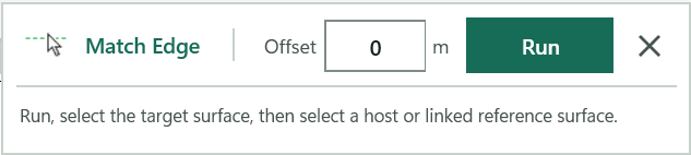
Vertical offset in metres added to every matched height; 0 makes the edges flush, a negative value keeps the target below the reference.
Starts picking: the target floor or toposolid first, then any number of references, each written as soon as you click it.
Tells you what to pick next and reports how many points were matched; press Esc to finish.
Open LandForm tab → Modify panel → Match Edge.
Set the offset. Type the vertical Offset in metres. Values between -10,000 and 10,000 are accepted; the status line asks you to correct anything else before Run becomes available.
Press Run and choose the target. Click the floor or toposolid whose edge should change. If exactly one editable surface was already selected when you pressed Run, LandForm uses it and skips straight to step 3; the status line says so.
Click the first reference. Click a floor or toposolid in the project, or click a floor, toposolid or model edge inside a loaded Revit link. The status line reads "Matching boundary elevations…" while LandForm works.
Clicking the target itself is refused with "Select a different reference surface".
Read the result. The status line reports "N points matched. Pick another reference, or press Esc to finish." Each reference is written to the model immediately in its own undo step named "LF-Match Edge", so you can undo one reference without losing the others.
If a reference gives "No points were created", its boundary does not cross the target in plan; pick another or press Esc.
Keep going around the target. Click every other surface the edge should meet. Shape editing is switched on for the target automatically if it was not already.
Press Esc to finish. The status line sums up: "N points matched from M reference(s)." Run again for another target, or close the toolbar.
The target floor or toposolid now carries new shape points along the stretch of its boundary that meets each reference, each sitting at the reference surface's height plus your offset. The two edges line up in section and the step between them is gone. Points are added where the target boundary crosses the reference boundary, where the target already had boundary corners over the reference, and, for a reference surface, where the reference's own fold lines cross the target edge, so the match follows a sloping or faceted neighbour rather than a single level. Where the reference was a linked edge, the target's existing boundary points on that edge are moved to the edge height instead of duplicated. Everything is native Revit shape editing, so Modify Sub Elements and the other LandForm terrain tools can refine it afterwards.
Vertical offset in metres added to every matched reference elevation. 0 makes the edges flush; a negative value holds the target edge below the reference. Accepts -10,000 to 10,000 m and is remembered between sessions.
Starts picking in Revit: the target floor or toposolid first (a single preselected surface is used automatically), then any number of reference surfaces or linked edges, each written to the target as soon as it is clicked. Press Esc to finish.
Closes Match Edge. Points already matched stay in the model.

Modify · Align Points
Align Points saves you placing and typing spot heights by hand when a surface has to tie in with something else: the underside of a bench or wall so it sits on the ground, the top of a kerb so the paving comes up flush, a 3D line that carries a design level, or the edge of a neighbouring slab. You choose a mode, pick the surface that should change, then pick the references. LandForm reads their elevations, adds or moves native shape points on the target, and leaves the result editable with Revit's own shape editing tools. References can be in the host model or in a linked Revit model.
LandForm tab→Modify panel→Align Points
Button tooltip: “Align surface shape points to selected objects, lines, or edges.”Align Points walkthrough. Until it is published, the steps and the annotated window below walk through the same workflow.
Numbers on the screenshot match the legend. Hover a number or a legend row to highlight the other.

Objects follows the faces of picked elements, Lines copies the elevations of picked lines, Edges makes the target meet a picked edge.
In Objects mode, brings the surface flush with the tops of the objects, or lets the objects sit on it.
In Edges mode, uses the picked edge only, or the whole top outline it belongs to.
Distance between sampled points along lines and edges, in metres.
Raises (positive) or lowers (negative) every written point, in metres.
Removes old interior points under the new ones first; boundary points are kept.
Starts the picks: the target surface first, then the references; Esc finishes.
Tells you what to pick next, counts the references and reports how many points were aligned.
Open LandForm tab → Modify panel → Align Points.
Choose a mode. Under Mode, pick Objects to follow the faces of picked elements, Lines to copy the elevations of picked lines, or Edges to make the target meet a picked edge.
In Objects mode, choose Top to bring the surface flush with the tops of the objects, or Bottom so the objects sit on the surface. In Edges mode, choose Segment for the picked edge only or Loop for the whole top outline that edge belongs to.
Set the numbers. Enter Step (m), the distance between sampled points along lines and edges, and Offset (m) to raise or lower every written point, for example a negative offset to leave room for a finish. Tick Clear inside if old interior points under the new ones should go first.
Run and pick the target. Click Run, then click the Floor or Toposolid that should receive the points. If exactly one suitable surface is already selected when you click Run, LandForm uses it and skips this pick.
Pick the references. Click the objects or lines to follow, one after another; the status line counts them. Press Esc when finished and LandForm writes all the points in one go.
In Edges mode every edge you pick is applied straight away and the status line reports the points aligned. Keep picking edges, and press Esc to finish.
Check and repeat. Read the result on the status line, check the surface in 3D or section, and click Run again for another target or another set of references. Close the toolbar with the X when you are done.
The target Floor or Toposolid now carries native shape points at the elevations of the references, plus the Offset you entered. In Objects and Lines modes the whole run is one undo step named "LF-Align Points"; in Edges mode each picked edge is its own "LF-Align Points" step, so you can undo one edge at a time. Points that already sit at a sampled position are moved rather than duplicated. The status line reports how many points were aligned, how many Revit refused and how many interior points were cleared. Nothing else about the target changes, and Revit's Modify Sub Elements tools still work on it.
The target follows the top faces or the undersides of the elements you pick. Faces are sampled at their vertices and every Step along their edges.
The target copies the elevations of the model or detail lines you pick, sampled every Step along each line.
The target takes the picked edge's elevation all along the edge, wherever the edge lies over the target in plan: target points within 45 mm of the edge are raised or lowered, and new points are added at the edge's corners and at each Step. Where the edge runs along or within 45 mm of the target boundary, the points go on the boundary itself.
Top: the target meets the top faces of the picked objects, so the surface comes up flush with them. Available in Objects mode.
Bottom: the target meets the undersides of the picked objects, so they sit on the surface. Available in Objects mode.
Edges: use only the picked edge.
Edges: use the whole top outline the picked edge belongs to, even when the top is made of many faces.
Step, in metres: the distance between sampled points along lines, edges and face outlines. Between 0.05 and 1,000 m; default 0.5 m.
Added to every written elevation, in metres. Positive raises the target above the reference, negative lowers it below.
Removes the existing interior points inside the outline of the new points before writing them. Boundary points are kept.
Starts the pick sequence: the target surface first, then the references. Press Esc to finish picking.
Closes the Align Points toolbar. Points already written stay in the model.

Modify · Project Family
Project Family fixes the trees, bollards, benches and light columns that float above or sink into the ground after the terrain has changed. You select the instances, and LandForm finds the surface under each one and moves it vertically onto it. Plan positions never change, only the elevation. By default it uses every Floor and Toposolid visible in the active view, including those in linked models; turn that off to project onto hosts you pick yourself.
LandForm tab→Modify panel→Project Family
Button tooltip: “Project family instances vertically onto visible or selected surface hosts.”Project Family walkthrough. Until it is published, the steps and the annotated window below walk through the same workflow.
Numbers on the screenshot match the legend. Hover a number or a legend row to highlight the other.

Lands the instances on every Floor and Toposolid visible in the view; untick it to pick the host surfaces yourself.
Also uses the Floors and Toposolids in linked models shown in the view; linked hosts are only read.
Limits the selection to one category, such as Planting; All Categories allows any point-based model family.
Select the instances and click Finish (or use the current selection); they move onto the surfaces in one undo step.
Status line; after a run it reports how many instances were projected and how many could not be resolved.
Open LandForm tab → Modify panel → Project Family.
Choose the hosts. Leave Visible hosts ticked to land on the Floors and Toposolids shown in the view, and tick Links if some of them are in a linked model. Untick Visible hosts if you want to name the surfaces yourself.
Limit the category (optional). Pick a category under Category, for example Planting, so a window selection only grabs those instances.
Run and select the instances. Click Run, then select the family instances and click Finish on the Options Bar. If instances are already selected when you click Run, LandForm uses them straight away.
Pick the hosts (only with Visible hosts off). Click each surface to project onto, in this model or in a link, and press Esc when done.
Check the result. The status line reports how many instances were projected and how many could not be resolved. If any failed, LandForm selects them so you can see which ones; otherwise it selects the moved instances.
Each projected instance has moved straight up or down so its insertion point sits on the top surface of the host below or above it; its plan position and rotation are unchanged. The whole run is one undo step named "LF-Project Family: Project Family Instances". The hosts themselves are not modified, and linked models are only read. Instances that miss every host, or that Revit refuses to move, stay where they were and are left selected after the run.
On (default): every Floor and Toposolid visible in the active view is a landing surface. Off: after selecting the instances, you pick the host elements yourself; Floors, Toposolids, roofs, walls, stairs, ceilings and topography surfaces are accepted, in the model or in a link.
On (default): with Visible hosts on, also uses the Floors and Toposolids in linked models shown in the view. Linked hosts are read only.
Limits which family instance category can be selected. All Categories allows any point-based model family.
Starts the run: select the instances (or use the current selection), pick hosts if Visible hosts is off, then the instances are moved onto the surfaces in one undo step.
Closes Project Family. Instances already projected stay where they are.
Not shown on the current toolbar. The projection always uses an offset of 0 m, so instances sit exactly on the surface.
Not shown on the current toolbar. When a vertical line misses a host edge, LandForm searches up to 0.1 m around the insertion point.
Not shown on the current toolbar; reading the offset from a parameter is off.
Not shown on the current toolbar; it is only used together with Param offset.

Modify · Rotate
Rotate is the quick fix for planting, furniture, bollards, boulders and any other point-based family that has been placed facing the wrong way. Drag the angle slider and every controlled instance turns about its own insertion point while you watch, so you can judge the result on the drawing before you keep it. Random gives a planting layout a natural, hand-placed look in one click, Edge and Perp set seats or lights parallel or square to a wall, kerb or path edge, and Match copies the orientation of one instance onto others.
LandForm tab→Modify panel→Rotate
Button tooltip: “Rotate point-based family instances with live preview and alignment tools.”Rotate walkthrough. Until it is published, the steps and the annotated window below walk through the same workflow.
Numbers on the screenshot match the legend. Hover a number or a legend row to highlight the other.

Pick the instances to control; the count beside it shows how many are under control.
Drag the slider or type a value from -180 to 180 degrees; it also sets the Random range and the Edge / Perp offset.
Reports the preview and how many instances were turned or skipped.
Keeps the previewed rotation as the new starting point and leaves Rotate open.
Turns every instance by the angle and keeps the result, like Apply.
Gives each instance its own random turn within plus or minus the angle.
Pick a reference edge, then an instance, to turn it parallel or square to that edge.
Keeps one picked edge so you can click many instances against it.
Copies the rotation of one picked instance onto each instance you click.
Turns every controlled instance back to the project orientation.
Open LandForm tab → Modify panel → Rotate.
Open a plan or 3D view. Start Rotate. The toolbar appears at the top of the view and all unpinned point-based instances in the view are selected and counted.
Choose the instances. If you only want some of them, press Select, pick the instances and finish the pick. Press Esc instead to keep the current set.
Preview an angle. Drag the slider or type a value in the box. After a moment every controlled instance turns about its own insertion point, from where it was when you last applied.
Keep it. Press Apply (or Fixed) to keep the rotation. The angle becomes the new starting point, so the next preview turns the instances further from here.
Randomise for a natural layout (optional). Set the slider to the largest turn you want, for example 45°, and press Random. Each instance gets its own random angle within plus or minus that range. Press Random again until the pattern looks right.
Align to an edge (optional). Set an Offset angle if the family's front is not along its own x-axis, then press Edge (parallel) or Perp (square). Pick a reference edge, then the instance to turn; repeat edge-then-instance pairs and press Esc when done.
Tick 1 ref first to pick one edge and then click as many instances as you like against it.
Match another instance (optional). Press Match, pick the instance whose rotation you want to copy, then click each target instance. Press Esc to finish.
Square up (optional). Press Reset to bring every controlled instance back to the project orientation.
Close. Press the × to close the toolbar. Any preview you did not apply is turned back first.
The instances keep their positions and only their rotation about the vertical axis through their insertion point changes. Each preview, apply, reset, alignment and match is a separate step in Revit's undo list, named "LF-Rotate Family Instances: Preview Rotation", "Apply Rotation", "Randomize Rotation", "Reset Rotation", "Align Rotation to Edge" or "Match Rotation", so you can step back through them with Undo after you close the toolbar. The status line reports how many instances were turned and how many were skipped.
Pick the unpinned point-based family instances to control, replacing the current set. Esc keeps the current set. Any unapplied preview is turned back first.
Turns every controlled instance by the Angle value from its last applied rotation and keeps the result.
Gives each instance a fresh random turn within plus or minus the Range value and keeps it. A range of 0 is set to 180 degrees first.
Turns every controlled instance back to the project orientation and resets the angle to 0.
Pick a reference edge, then an instance; the instance turns parallel to the edge in plan plus the Offset angle. Esc finishes.
Pick a reference edge, then an instance; the instance turns perpendicular to the edge plus the Offset angle. Esc finishes.
Keeps one picked edge for Edge and Perp so you can click many instances against it.
Pick one source instance, then click target instances to give them the same rotation. Esc finishes.
Sets the angle, range or offset from -180 to 180 degrees and previews the rotation in the model as you drag.
Exact angle, range or offset in degrees; stays in step with the slider.
Keeps the current preview as the new starting rotation and leaves Rotate open. Enter does the same.
Closes Rotate and turns any unapplied preview back to the last applied rotation.

Modify · Array
Array is the tool for a row of trees along a curving avenue, bollards around a kerb, lights along a promenade or bench seats around a plaza. Revit's own array only works along a straight line or a radius; here the path can be any polyline, arc chain or smooth curve, an existing model edge, or a chain of connected lines. You see cyan preview copies before anything is committed, and the finished array remembers its path and settings, so you can reopen it later and change the spacing or reshape the route.
LandForm tab→Modify panel→Array
Button tooltip: “Copy a family instance along a drawn or selected path.”Array walkthrough. Until it is published, the steps and the annotated window below walk through the same workflow.
Numbers on the screenshot match the legend. Hover a number or a legend row to highlight the other.

Pick the family instance to copy along the path; Esc keeps the current source.
Choose the source from a list of every family Array can copy, filtered by Category or Search.
Shows the category and ID of the source once you have picked it.
Shape of the path between points: Line, Line + Arc, Arc, Spline or Bezier.
Click the path points in the view; Esc finishes.
Use visible model edges, or a model or detail line and every line joined to it end to end, as the path.
By spacing places items a fixed distance apart in metres; By count spreads a fixed number along the path.
Close the loop, reverse the station order, turn each copy to the path, and place items exactly on the path ends.
Shifts every item sideways from the path, in metres: positive to the left of the path direction, negative to the right.
Moves one path point by picking, for elevations, sections and perspective views where grips are not shown.
Removes the last path point, or the whole path.
Tells you what to do next; the item count appears at its right end.
Places the copies, saves the array settings and closes the toolbar.
Reloads a saved array from one of its items so you can change it and run it again.
Open LandForm tab → Modify panel → Array.
Choose the source. Press Pick Family and click the instance to copy; its category and ID appear beside the buttons. If you selected an instance before opening Array, it is used straight away.
Press Families… instead to choose from a list of every family Array can copy, filtered by Category or Search. A family that is not placed yet gets one instance at the start of your path, and that instance becomes the first item.
Pick the path style. In Path, choose Line for straight segments, Arc or Line + Arc for arcs through each set of three points, Spline for a smooth curve through every point, or Bezier for a softer smoothed curve.
Draw or pick the path. Press Draw and click the path points in the view; the next segment follows the cursor, and the preview copies update after each click. Press Esc when the path looks right.
Or press Pick Edges and pick one or more visible model edges, then Finish, or press Connected Lines and pick one model or detail line: every line joined to it end to end is used too.
Set the distribution. Choose By spacing and enter Spacing in metres, or By count and enter Count. Tick Start and End to place items exactly on the path ends, Closed to join the last point back to the first, and Align to turn each copy to the path direction.
Offset the row (optional). Tick Offset and enter a distance in metres to shift every item sideways from the path, for example to set trees back from a kerb line. Positive values shift to the left of the path direction, negative to the right.
Adjust the path. In plan and 3D views, drag the square grip on any path point; the preview updates when you let go. In elevations, sections and perspective views, use Move Guide: pick a grip, then pick its new location. Undo removes the last path point and Clear removes the whole path.
Run. Check the item count at the right of the status line and press Run. LandForm places the copies, saves the array settings and closes the toolbar.
The model now holds one copy of the source family at every station along the path; the source itself stays where it is and counts as an item when it sits on a station. All copies are ordinary family instances that you can schedule, tag or edit like any other. The whole placement is one undo step named "LF-Path Array: Create or Update Array". The path, settings and member list are stored on the source, the copies and any picked path elements, so Edit Saved can reload the array later.
Pick the family instance to copy along the path. Esc keeps the current source.
Choose the source from a list of the families Path Array can copy, when it cannot be picked on screen. A placed family is copied from one of its instances; a family that is not placed yet gets one instance at the start of the path, which becomes the first item.
Reload a saved Path Array, with its path and settings, from a selected or picked member so you can change it and run it again.
Shape of the path between guide points: Line, Line + Arc, Arc, Spline or Bezier.
Click guide points in the active view, adding to the current path; Esc finishes. Points snap to endpoints, midpoints, intersections and the work plane grid.
Pick one or more visible model edges and press Finish to use them as the path.
Pick one model or detail line; every line of the same kind joined to it end to end becomes part of the path.
Move one path guide point by picking. In plan and 3D views every path point also carries a square grip: drag it to reshape the path, and the array preview updates when you let go (Esc cancels a drag). Move Guide covers elevations, sections and perspective views, where grips are not shown.
By spacing places items a fixed distance apart; By count spreads a fixed number of items along the path.
Distance between items along the path, in metres (at least 0.01). Used with By spacing.
Number of items along the path. Used with By count.
Joins the last path point back to the first and spaces the items around the loop.
Reverses the station order along the path; a family placed new from Families… then starts at the far end.
Turns every copy to follow the path direction at its station.
Places an item exactly on the path start.
Places an item exactly on the path end (ignored for a closed path).
Shifts every item sideways from the path by the offset distance.
Signed sideways offset in metres: positive to the left of the path direction, negative to the right.
Removes the last path guide point.
Removes the whole path so you can start again.
Creates the array, or replaces the copies of the saved array you are editing, then closes the toolbar.
Closes Path Array and removes the preview copies without placing anything.

Modify · ToFamily · In-Place Family
Model-in-place components are quick to sketch but awkward to live with: they cannot be copied between projects, scheduled as types or reused from a library. In-Place Family takes the solid geometry of each in-place instance you choose, builds a new family from a Revit family template, saves it as an RFA file with a name you control, and can load it back into the project, place it exactly where the original stood and remove the original. You can convert a whole batch of planters, seats or sculpted landforms in one run.
LandForm tab→Modify panel→ToFamily ▾→In-Place Family
Button tooltip: “Convert model-in-place solids into loadable Revit families.”In-Place Family walkthrough. Until it is published, the steps and the annotated window below walk through the same workflow.
Numbers on the screenshot match the legend. Hover a number or a legend row to highlight the other.
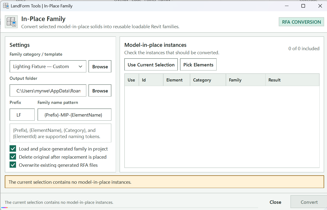
Returns to Revit so you can pick model-in-place instances; Esc keeps the current list.
Replaces the list with the model-in-place instances in the current Revit selection.
One row per instance: clear Use to leave a row out, and read Result after a run.
Counts how many rows will be converted.
Chooses the Revit family template for the new families; Browse picks any other .rft file.
Where the RFA files are saved; Browse chooses the folder.
Name each new family from {Prefix}, {ElementName}, {Category} and {ElementId}.
Loads each new family and places an instance where the original stood; clear it to create the RFA files only.
Removes the in-place element once its replacement is placed.
Replaces a file of the same name; when cleared, new files get a number added.
Tells you what is missing before you can run, and shows progress during the run.
Generates a family for every included instance, and loads and places it when that option is on.
Closes the window and saves the current settings.
Open LandForm tab → Modify panel → ToFamily ▾ → In-Place Family.
Bring in the instances. Select the model-in-place elements in Revit and start In-Place Family; they are listed straight away. Otherwise press Pick Elements, pick them in the view and finish the pick, or select them in Revit and press Use Current Selection.
Choose what to convert. Clear the Use tick on any row you want to leave alone. The count at the top right shows how many rows are included.
Choose the family template. Pick a template from Family category / template; the list holds the loadable model templates installed with Revit and starts on Generic Model. Press Browse to use any other .rft file.
Set where and how files are saved. Enter or Browse to the Output folder, then set Prefix and Family name pattern. The pattern can use {Prefix}, {ElementName}, {Category} and {ElementId}; the default {Prefix}-MIP-{ElementName} gives names such as LF-MIP-Planter.
Decide what happens in the project. Leave Load and place generated family in project ticked to load each new family and place an instance where the original stood, and Delete original after replacement is placed to remove the in-place element in the same step. Clear the first option to create the RFA files only.
Clear Overwrite existing generated RFA files to keep older files; new ones then get a number added to their name.
Run. Press Run. The progress bar moves through the list and the Result column reports each row as converted, with its file name, or skipped, with the reason.
Check the summary. The Last run box shows how many instances were converted and skipped and the output folder. Close the window when you are done, or pick more instances and run again.
Each converted instance now has its own RFA file in the output folder, containing its solids as free-form geometry, with the family category set to the original element's category whenever the template allows it. With loading on, the family is loaded into the project and one instance is placed at the centre of the original geometry, on the same Workset, so it lines up with where the in-place element was. Each replacement is its own undo step named "LF-In-Place Family: Load and Place Replacement". Your settings are remembered for the next time you open the tool.
Chooses the Revit family template for the new families, from the loadable model templates installed with Revit. Generic Model is the default.
Picks any Revit family template file (.rft) from disk and adds it to the list.
Folder where the generated RFA files are saved; it is created if it does not exist.
Chooses the output folder for the generated family files.
Text inserted wherever the name pattern contains {Prefix}.
Name of each new family, built from {Prefix}, {ElementName}, {Category} and {ElementId}.
Loads each new family and places one instance where the original stood. When cleared, LandForm only creates the RFA files.
Deletes a source model-in-place instance only after its replacement family instance is placed. Available only while loading is on.
Replaces a file of the same name. When cleared, LandForm adds a number to avoid replacing an existing family file.
Replaces the list with the model-in-place instances in the current Revit selection.
Returns to Revit so you can pick model-in-place instances; only in-place elements can be picked. Esc keeps the current list.
One row per instance: tick Use to include it, and read the Result column after a run.
Generates a family for every included instance and loads and places it when that option is on.
Closes In-Place Family and saves the current settings.

Modify · ToFamily · Lines to Detail Item Family
When you have drawn a paving joint, a tree pit edge or a fixing detail with detail lines and want to reuse it, this tool saves you the round trip through the Family Editor. Select the lines, give the family a name, click an insertion point, and LandForm builds the family from Revit's Detail Item template, loads it, places one instance on the same spot and can delete the loose lines. From then on the detail is a single component you can copy, schedule and swap.
LandForm tab→Modify panel→ToFamily ▾→Lines to Detail Item Family
Button tooltip: “Convert detail lines into a loadable Detail Item family.”LF-DT- followed by at least five descriptive characters, for example LF-DT-Tree Pit Edge.Lines to Detail Item Family walkthrough. Until it is published, the steps and the annotated window below walk through the same workflow.
Numbers on the screenshot match the legend. Hover a number or a legend row to highlight the other.

Type the rest of the family name after LF-DT-; the list shows the Detail Item families already in the project.
Confirms the name is available or tells you what to change, here to add at least five descriptive characters.
Removes the source lines once the family is placed; clear it to keep them.
Creates, loads and places the family; it stays greyed out until the name is valid.
Open LandForm tab → Modify panel → ToFamily ▾ → Lines to Detail Item Family.
Select the lines (optional). Select the detail lines in the active view before you press Run. If nothing suitable is selected, LandForm asks you to drag a window around them instead.
Name the family. The Name box starts with LF-DT-; type the rest of the name. The status line confirms "This name is available." or tells you what to change. Open the list to see the Detail Item families already in the project.
Choose whether to keep the lines. Leave Delete lines ticked to remove the source lines once the family is placed, or clear it to keep them.
Run. Press Run. If you did not preselect lines, drag a window around them now. Press Esc at any prompt to cancel.
Pick the insertion point. Click the point in the view that should become the family origin.
Check the result. The new family is loaded and one instance is placed at the insertion point, so it sits exactly over the original lines. The status line reports that the family was loaded and placed.
Repeat or close. Enter another name and press Run for the next detail, or close the toolbar with ×.
The project now contains a new Detail Item family with one type, built from your lines and placed once in the current view at the point you picked. If Delete lines was ticked, the source lines are gone. Loading, placing and deleting are one undo step named "LF-Lines to Detail Item Family: Load and Place Family", so a single Undo puts the lines back.
Name of the new family, normally LF-DT- followed by at least five descriptive characters. The list shows the Detail Item families already in the project, so you can avoid their names.
Deletes the source detail lines once the new family instance is placed. Clear it to keep the lines.
Uses the selected detail lines, or asks you to window-select them, then asks for the insertion point and creates, loads and places the family.

Modify · Contour · Line Elev
When you trace contours from a survey drawing, every model line ends up flat on the same level. Set Line Elevations (Line Elev on the ribbon) moves them to the heights they represent, so they can drive a Toposolid or be checked in 3D. Pick one line and LandForm moves the whole connected contour; or select many contours, show the direction they climb, and LandForm gives each one the next elevation in the sequence.
LandForm tab→Modify panel→Contour ▾→Line Elev
Button tooltip: “Set model-line elevations for contour and grading workflows.”Set Line Elevations walkthrough. Until it is published, the steps and the annotated window below walk through the same workflow.
Numbers on the screenshot match the legend. Hover a number or a legend row to highlight the other.

Height of the contour in metres; in Multiple mode, the height of the first contour.
Single sets one connected contour; Multiple steps a series of contours by the interval.
Height step between neighbouring contours in Multiple mode; negative values step down.
Tick it to give the moved lines the line style chosen beside it.
Starts picking: one contour line in Single mode, or the contours and then a direction in Multiple mode.
Tells you what to pick and reports how many model lines were updated.
Open LandForm tab → Modify panel → Contour ▾ → Line Elev.
Enter the elevation. Type the height of the contour in Elevation.
Choose the mode. Pick Single to set one contour, or Multiple to set a series and enter the Interval between them.
Set the line style (optional). Tick Style and choose a line style if the moved lines should change style as well.
Single: pick one line. Press Run and click any segment of the contour. That line and every model line joined to it end to end in the active view move to the Elevation.
Multiple: select the contours. Press Run, select all the contour lines in the series and press Finish on the options bar.
Multiple: show the direction. Click a start point on any visible element near the first contour, then a second point in the direction the contours climb. The contours are taken in the order they lie along that direction: the first gets the Elevation, the next one Elevation plus Interval, and so on across the selection.
Carry on. The status line reports how many model lines were updated. Change the values and press Run again for the next contour or series, or close the toolbar when you are done.
The model lines keep their plan shape and now sit on horizontal work planes at the new heights, so a 3D view shows the contours stacked at their real levels. Each run is one step in Revit's Undo list: "LF-Set Line Elevations: Set Line Elevation" for Single and "LF-Set Line Elevations: Set Elevations by Direction" for Multiple.
Contour elevation in metres, from the Revit internal origin. In Multiple mode it is the height of the first contour of the sequence.
Pick one model line; it and every model line connected to it end to end move to the elevation.
Select several contours, then pick a start and a direction point; each contour group gets the next elevation by interval.
Elevation step in metres between neighbouring contours in Multiple mode. Negative values step down.
Change the line style of the moved lines to the style chosen beside it.
Line style applied to the moved lines when Style is ticked.
Start picking model lines (and, in Multiple mode, the start and direction points).
Close the Set Line Elevations toolbar.

Modify · Contour · Contour Draw
Contour Draw is for shaping landform the way you would on tracing paper. You set a start level and an interval, click a contour, press Esc, and the work plane steps up to the next level so you can draw the next one straight away. While you draw, LandForm shows where the current level and the next one cut the existing ground, so new contours can tie in where they should. When the contours are done, one click builds a Toposolid from them or reshapes an existing Toposolid or Floor.
LandForm tab→Modify panel→Contour ▾→Contour Draw
Button tooltip: “Draw model-line contours level by level from a compact toolbar.”Contour Draw walkthrough. Until it is published, the steps and the annotated window below walk through the same workflow.
Numbers on the screenshot match the legend. Hover a number or a legend row to highlight the other.

The survey elevation of the current contour; the target button beside it picks the level from the model.
How far the level steps after each contour; a negative interval steps downhill.
Spline from control points, spline through every point, or Revit's own Model Line tool.
Starts drawing at the current level; Esc finishes the contour and steps to the next level.
The keys for the current mode.
Traces a contour you click on a visible Toposolid or Floor, with grips to adjust it.
Reshapes a picked contour; the list sets whether a click moves, adds or removes points.
Builds a new Toposolid from the Contours, a Drawn Area or an Enclosed Area.
Raises or lowers a newly created Toposolid relative to the contours.
Pushes the contours into a picked Toposolid or Floor as shape points.
Removes existing interior points within the tolerance of each contour first.
Deletes the contours drawn in this session, after asking.
Tells you the next step and what the last action did.
How many contours sit at the current level and in total.
Open LandForm tab → Modify panel → Contour ▾ → Contour Draw.
Set the start level. Type the Elev of the first contour and the Interval, or use the arrows: Elev steps by one interval and Interval by 0.05 m.
Or press the target button beside Elev and click the model. On a Toposolid the level snaps to the nearest visible contour; on a floor, a linked CAD or Revit file or any other geometry it takes the exact height you clicked. Drawing starts at that level right away.
Choose the mode. Spline (control pts) shapes the contour from control points, Spline (through pts) passes it through every point you click, and Revit draw opens Revit's own Model Line tool on a work plane at the level.
Draw the contours. Press Draw and click the points of the first contour. The work plane grid appears at the current level; an amber line shows where that level cuts the visible Toposolids and Floors, amber dots mark where it leaves a surface, and a thinner cyan line shows where the next level will run.
Press Esc to finish the contour: it is created as a model line, the level steps by one Interval and the next contour starts. Press Esc again with no points to pause. In Revit draw mode, press + for the next level and - for the previous one.
Trace an existing contour (optional). Press Auto Trace and click near a contour on a visible Toposolid or Floor. LandForm traces it, smooths it and shows it as a pink preview with grips; adjust the grips and press Esc to create the line.
Reshape a contour (optional). Press Edit Points and pick a contour; it is reduced to a few grips at its own level. The box beside the button sets what a click does: Move grips (Ctrl+click removes a grip), Add points (clicks past either end extend the line) or Remove points. Esc moves on to the next contour, a second Esc ends editing.
Build a new Toposolid. On the second row, under New from, press Contours, Drawn Area or Enclosed Area (see the table below). Set Offset first if the surface should sit above or below the contours, for example a negative value to leave room for a paving build-up.
Or reshape an existing surface. Press Apply Contours and pick the Toposolid or Floor. The contours become shape points at their own elevations. With Clean pts on, existing interior points within Tol of each contour are removed first so old and new levels do not fight.
Tidy up. Press Clear Lines to delete the contours drawn in this session, or close the toolbar, which removes them along with the work plane grid.
Each hand-drawn contour is a model line on a horizontal work plane at its own level, and each is a separate Undo step such as "LF-Contour Draw: Draw Contour at 12.50 m". The curve count on the right of the status line shows how many contours sit at the current level and in total. A new Toposolid uses the first Toposolid type in the project and the level of the active plan (or the lowest level), and is one Undo step, "LF-Contour Draw: Create Toposolid from Contours". Apply Contours adds the shape points in one step, "LF-Contour Draw: Add Contour Points to Surface" (or "Replace Surface Contours" with Clean pts on), reports any points that fell outside the surface or on its edge, and then removes the lines this tool drew.
The toolbar has two rows, one for each job the tool does, with the status line underneath.
Contours. The top row makes and edits contour lines: Mode, Elev with its pick button, Interval, then Draw, Auto Trace, Edit Points with its click mode, and Clear Lines. The shortcut reminder beside them changes with the mode.
Toposolid. The bottom row turns lines into terrain. There are three ways to create a new Toposolid:
| New from | Use it when |
|---|---|
| Contours | The contour lines already cover the area. Their own shape becomes the outline. Uses this session's lines, or asks you to select some. |
| Drawn Area | You want to set the outline yourself. Click the corners and press Esc to close the shape; then click an edge's midpoint grip and click where it should sit to bend that edge into an arc. A second Esc builds the Toposolid, with its edge matched to the surfaces around it and the contours inside draped onto it. |
| Enclosed Area | Paths, kerbs, steps, walls or railings already ring the space. Select them and the open area between them is filled, with its levels read from the surrounding surfaces. A selected element standing inside the area is left out as an opening. |
Beside those, Existing › Apply Contours reshapes a Toposolid or Floor that is already there, with Clean pts and Tol controlling the clean-up of nearby old points, and Offset shifts any newly created surface.
You do not have to draw contours first: Drawn Area and Enclosed Area both work with no contours at all.
No separate LandForm window. This command runs directly from Revit selection and prompts; follow the workflow above and the messages shown beside the cursor or on Revit's status bar.
LandForm ribbon panel
Planting libraries, mixes, palettes, connectors and schedules.

Softscape · Planting · Planting Library
Planting Library is the office plant palette inside Revit. Trees, palms, xeriscapes, shrubs, groundcovers, ornamental grasses, climbers, lawns and indoor plants sit in one window with instant search, filter chips, a table or photo-card view and a detail panel that sketches the family before it exists. Check the records you need and press one button: trees, palms, xeriscapes, climbers and indoor plants become generated Planting families, while shrubs, groundcovers, ornamental grasses and lawns become Toposolid types (with optional placeable families). The same window updates content already in the project, opens the in-place editor for a one-off exception, loads matching tags and builds schedules.
The library reads the bundled LandForm catalog or your own company workbook, so the office keeps editing one Excel file and every project reads from it.
LandForm tab→Softscape panel→Planting ▾→Planting Library
Button tooltip: “Manage, search, and update the shared plant library in one place.”Planting Library walkthrough. Until it is published, the steps and the annotated window below walk through the same workflow.
Numbers on the screenshot match the legend. Hover a number or a legend row to highlight the other.
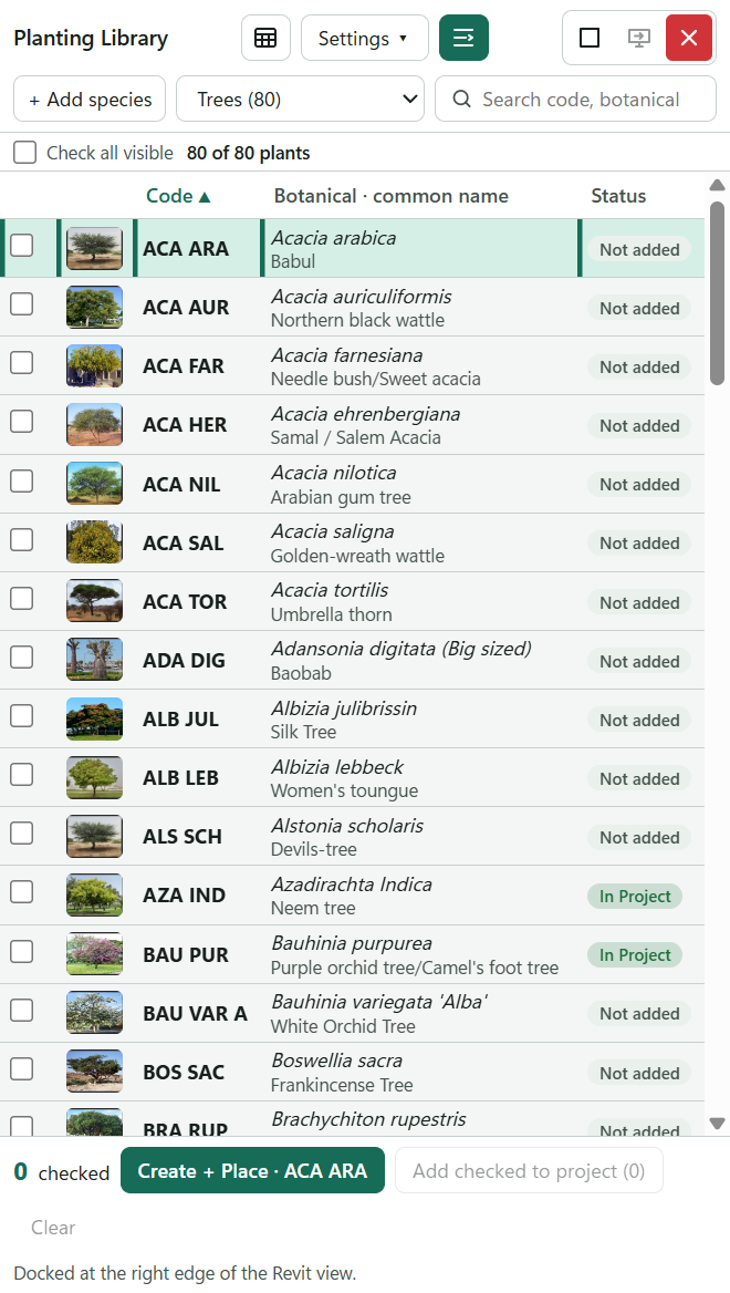
Chooses the plant category; the number is how many records it holds.
Every word must match the code, botanical or common name, form, water need, tolerances or remarks. Press / to jump here.
One row per plant with its photo, code, botanical and common name. Click a row to make it active; click a heading to sort.
Shows whether each plant is Not added or already In Project.
Tick the plants to create; Shift-click a box to check a range.
Checks every plant the filters currently show; the count beside it gives the plants shown.
Counts the checked plants; Clear unchecks everything, including rows hidden by filters.
Creates every checked plant without a placement pick.
Creates the one checked plant, or the highlighted row when nothing is checked, and asks for the planting point. Enter does the same.
Reports loading, progress and the final report of each create or update.
Opens Create a schedule for a plant schedule or formatted schedules per category.
Docks the library as this narrow strip on the right edge of the view; press it again to fit the full window back.
Library actions: company library, reload, edit source, save as library, naming standards, workbook guide and matching tags.
Appends a new record to the editable company workbook; enabled only while one is active.
Open LandForm tab → Softscape panel → Planting ▾ → Planting Library.
Let the catalog load. The status line reports progress per category and ends with "N records loaded from …". The source badge at the top names the active workbook (green border when it is editable, amber when a sheet fell back to the bundled catalog); click it to open the workbook guide.
Pick a category. The left rail lists All plants, then the categories grouped as Created as families (Trees, Palms, Xeriscapes, Climbers & Creepers, Indoor Plants) and Created as Toposolid types (Shrubs, Groundcovers, Ornamental Grasses, Lawns), each with its record count.
Narrow the list. Type in Search (press / to jump to it); every word you type must match somewhere in the code, botanical or common name, form, water need, tolerances or remarks. Click the Project status, Form, Water need and Drought tolerance chips, or tick Native only and With photo only; Clear removes the filters. Switch between Table and Cards, click a column header to sort, and use Group by to section the table by category, form, water need or status.
Review a plant. Click a row to show it in the right-hand panel: the photo, the family preview sketch (with the clear zone it will plant into), botanical and common name, plant code, form, mature size, installation size, water need, native and adaptive status, pot size, drought and salinity tolerance, source and remarks. Hover any thumbnail to zoom it; right-click a row for a short action menu.
Check the records you want. Tick the box, double-click a row, or Ctrl/Shift-select several rows and press Space. Shift-click a box to check a range, or tick Check all visible for everything the filters currently show. Compare lays up to eight checked plants side by side; Clear unchecks everything, including rows hidden by filters.
Decide about low planting families. When shrubs, groundcovers or grasses are checked, Also create families appears in the footer. Leave it off to create Toposolid types only; tick it to generate placeable Planting families as well.
Create the content. Press Add checked to project (N) to create every checked record without a placement pick. To place one plant, use Create + Place in the detail panel or the right-click menu (it reads Create type for Toposolid categories): the record is created and Revit asks you to pick the planting point. The footer shows item-by-item progress and the final report, and the matching planting tags are refreshed automatically.
Update later. When the workbook changes, check the records and press Update checked (N). Only records already In Project are updated; their generated names, materials, type images and family geometry are brought in line and every placed instance keeps its location.
Customise one plant (optional). Edit / Customize… opens the in-place Planting Editor for the active record so you can preview it in Revit and override its form, size or installation graphics for this project. Lawns cannot be edited here; change their thickness in the workbook.
Build schedules. The schedule button opens Create a schedule: Plant schedule makes one schedule for every category, sectioned with subtotals, and the formatted schedule buttons make one schedule per category that mirrors the workbook columns (a Planting schedule for family categories, a Toposolid schedule for low planting and lawns). They appear in the Project Browser under Schedules.
Every checked plant now exists in the project: generated Planting families for trees, palms, xeriscapes, climbers and indoor plants, Toposolid types for shrubs, groundcovers, grasses and lawns, and both when Also create families was on. The library data travels with the content as planting parameters, the plant code is written to Type Mark and the botanical name to Description so stock tags and schedules read them, and the workbook photo becomes the Type Image. The row's status switches to In Project. Family creation runs as the generator's own undo steps ("LF-Planting Family Generator: Load Family" and "LF-Planting Family Generator: Place Family"); schedules are created as "LF-Planting Library: Create Plant Schedule" and "LF-Planting Library: Create Formatted Schedule".
Plant Code and Botanical Name, and also read Common Name, Native, Adaptive, Irrigation Classification, Pot Size, Caliper, Installation Size, Mature Height, Mature Spread, Drought Tolerance, Salinity Tolerance, Form and Remarks. Sizes are text; the first number in the cell drives the geometry.Asset ID, Plant Code, Botanical Name, Common Name, Category, Native, Irrigation Classification, Pot Size, Installation Height m, Installation Spread m, Mature Height m, Mature Spread m, Density, Planting Form, Default Output, Variation Seed, Library Version and Remarks. The four … m columns must be plain numbers.Picture, Image or Photo, as a picture anchored to the cell, an Excel in-cell picture or a file path. A record without a photo borrows the bundled one for the same code or botanical name.Density sets the plant count of area planting: 4 means 4 plants per m², 0.5 m, 500 mm or 45 cm is a centre spacing on a triangular grid, and adding square switches to a square grid.LF_PlantingParameters.txt), and the two-way link between Type Mark/Description and the library code/botanical name. Turn the link off if your office uses Type Mark for keynotes./ focuses the search, Up/Down move the highlight, Space checks the selection, Ctrl+A selects every visible row, Esc clears the search or closes a menu or dialog.Collapse the library to its header while editing a plant.
Import, edit, export, or schedule the plant library.
Load a company library workbook, reload it after edits, or return to the bundled library.
Append a new record to the active editable library workbook.
Export every catalog sheet into one editable workbook that any company can maintain and share.
Create or refresh a schedule mirroring the active category's Excel columns: same fields, same order, headers without the LF_ prefix. Trees, palms, and other loadable plants create a Planting schedule; shrubs, groundcovers, grasses, and lawns create a Toposolid schedule.
Chooses the plant category to browse; the number beside each category is how many records it holds.
Shows only records with one project status, for example those already In Project.
Filter by canopy or planting form.
Shows only records with one irrigation classification (water need).
Shows only records whose native status reads NATIVE.
Check or clear every row currently shown by the filters.
Clear every checked batch row, including rows hidden by filters.
The spreadsheet-style catalog: code, botanical and common name, form, mature size, water need and project status. Click a row to review it; tick Batch to include it.
Include this record. Shift-click checks a range; Ctrl/Shift-select rows and press Space to toggle them together.
Show the spreadsheet-style catalog, filters, and batch selection tools.
Choose a plant category.
Search plant code, botanical name, common name, or traits.
Check or clear every row currently shown by the filters.
Ctrl-click selects separate rows; Shift-click selects a range. Checking a highlighted row applies to the highlighted selection.
Include this record. Shift-click checks a range; Ctrl/Shift-select rows and press Space to toggle them together.
Applies to shrubs, groundcovers, and ornamental grasses. Tree and xeriscape records always generate a Planting family.
Create content for every checked row: Toposolid types for low planting, generated Planting families for trees and xeriscapes.
Create only the active row's content and place its Planting family at a picked point.
Update checked library content that is already in the project.
Open the in-place editor to preview the plant in Revit and override its 3D form, dimensions, or installation graphics for a project-specific exception. Available for tree and xeriscape records.
Library category, and therefore the workbook sheet, the new record is appended to.
Plant code, required. It must be unique within the sheet and is the key used by type names, tags and schedules.
Botanical name, required.
Common name, optional.
Mature height in metres, required; it drives the family geometry.
Mature spread in metres, required; it drives the family geometry.
Installation height in metres, optional.
For example NATIVE or ADAPTIVE.
For example LOW, MEDIUM, or HIGH.
Free-text remarks stored with the record and shown in the detail panel.
Closes the dialog without adding a record.
Appends the record to the active editable workbook and reloads the library.

Softscape · Planting · Section Planting
Sections through a landscape usually show planting beds as bare ground lines, and dressing them by hand means placing and mirroring dozens of 2D shrubs per view, then doing it again whenever the ground changes. Section Planting reads the Toposolid and floor planting beds in the active section or elevation and places LandForm elevation symbols along them. You decide once which symbols each planting type uses by dragging them onto the type in a mapping studio; LandForm works out the spacing, sizes, mirroring and draw order, and lays the beds behind the cut super light so the drawing reads in depth.
LandForm tab→Softscape panel→Planting ▾→Section Planting
Button tooltip: “Stand 2D shrub and groundcover elevations on the planting beds a section shows.”Section Planting walkthrough. Until it is published, the steps and the annotated window below walk through the same workflow.
Numbers on the screenshot match the legend. Hover a number or a legend row to highlight the other.
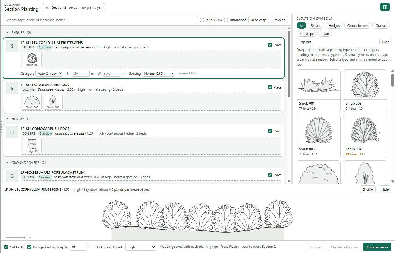
The section or elevation being dressed and how many plants it already holds.
Find a type by name, code or botanical name; In this view and Unmapped narrow the list.
Gives every unmapped planting type symbols that suit its category.
Reads the Toposolid and floor types from Revit again after you change them.
Drop a symbol here to map every type in the category at once.
The elevation symbols used for this type; several symbols are mixed along the bed.
Shown for the selected type: category override, height and width in metres, and automatic or manual spacing.
Untick to leave this type out when placing.
Moves the type list, the symbols and the preview into a window of their own for mapping; Back to the panel or closing it brings them back.
Folds the symbol gallery away in the docked panel; the symbols already on the types stay.
Show all symbols or only shrubs, hedges, groundcovers, grasses, xeriscape or lawn.
Drag a symbol onto a type or a category heading to map it.
The selected type's plants laid out along a bed, with a 1 m scale bar.
Another random arrangement; changes the preview only.
Cut beds, Background beds up to a distance in metres, and how Background plants are toned down.
Places the mapped plants in the active section or elevation.
Lays the plants out again in every view that holds them.
Deletes the Section Planting plants in the active view; pinned plants stay.
Open LandForm tab → Softscape panel → Planting ▾ → Section Planting.
Open the section. Make the section or elevation you want to dress the active view, then start Section Planting from Softscape › Planting ▾.
Review the planting types. The studio lists the Toposolid and floor planting types (floor types carry a *floor* tag), with each plant's category (shrub, groundcover, grass, hedge or lawn) and suggested height from the library. Change Category if LandForm guessed wrong; type names containing *hedge* are treated as hedges. Press Re-read after changing types in Revit.
Map the symbols. Drag one or more elevation symbols from the symbol library onto each planting type. Several symbols on one type are mixed along the bed for a natural look. Press Auto-map to give every unmapped type a suitable symbol for its category. On one screen, press Pop out above the symbols to map in a window of its own: the type list and the symbols side by side, as large as you like, and on a second screen if you have one; Back to the panel, or closing that window, brings them back. In the docked panel the symbol strip and the preview fold away with Hide, the bar above the symbols drags the strip taller or shorter, and a type's category, size and spacing editors open when you select it.
Set the spacing (optional). Leave spacing on automatic, which uses the plant's mature spread, or choose Manual (m c/c) and enter a centre-to-centre distance, prefilled from the library planting density. Hedges and lawns are laid continuously and have no spacing.
Preview. Select a type to preview its plants along a bed. Press Shuffle for another random arrangement; the preview only changes the studio, not the model.
Place. Choose which beds to dress at the bottom of the studio: Cut beds for the beds the section cuts, Background beds up to a distance in metres behind the section line, and how Background plants are toned down: Light (the default: halftone grey that still reads as planting), Lighter, Lightest (barely there), Halftone only or As drawn. The three grey choices get paler the farther a bed stands behind the section line. Press Place in view. LandForm builds one 2D family per symbol and size, named like *LF-ELEV-Shrub 002 950x900*, and stands the plants on the cut beds and on the beds visible behind the section line. The status line then says what was not dressed: beds of planting types that have no symbols yet, and Planting families standing in the view.
With Earth hatch ticked, the same Place also hatches the earth under the ground the section line cuts, exactly at the line, and draws the ground line over it in Wide Lines. The earth starts at the top of Toposolids and planting floors, and under paving and other floors below the floor's type thickness. It then runs down through the layers beneath to the underside of the cut ground. A deck standing clear above the ground is skipped, and walls, planters and steps cut by the line stay clear. Pick the filled region type beside the option and how deep it reaches: Cut ground bottom, or 0.5 to 5 m below the lowest cut ground. LF Section Earth is LandForm's own type: the project's Earth pattern in grey with masking, made only when the project lacks it. With Wall hatch ticked, every wall the section line cuts gets a concrete filled region of its exact cut face, outlined in Wide Lines. LF Section Concrete is LandForm's own type, using the project's Concrete pattern in grey with masking; pick another filled region type beside the option if your office has one. The earth and wall hatches are drawn in front of the plants, so plant parts below the ground line or across a wall are covered.
Update after design changes. When the ground, the beds or the mapping change, press Update all views to lay the plants out again in every view that holds them.
Remove (optional). Press Remove to delete the Section Planting plants in the active view.
The view shows 2D elevation plants standing on its planting beds, sized from each plant's mature height and the symbol's proportions, spaced along each bed with slight size variation, every other plant mirrored. Their draw order follows depth: nearer plants sit over farther ones and the cut rows over all, so each plant masks only what stands behind it. Each planting type gets its own family type named like the Toposolid or floor type, with the plant code as Type Mark and the botanical name as Description, so the plants can be tagged and scheduled. The mapping is saved with each planting type, so the next section in the project starts from the same choices.
No separate LandForm window. This command runs directly from Revit selection and prompts; follow the workflow above and the messages shown beside the cursor or on Revit's status bar.

Softscape · Planting · Planting Editor
Library plants are generated from approved values, but a project often needs an exception: a taller clear trunk over a footpath, a narrower crown in a courtyard, a different plan symbol for one drawing set, or a clear zone and staking shown for the planting details. Planting Editor opens the same customise panel as the Planting Library directly on a plant you click in the model. The plant you picked is hidden while you edit and a preview takes its place, so you see each change in context. When you press Update Existing, the family is rebuilt and reloaded, and every placed instance of it keeps its own position.
LandForm tab→Softscape panel→Planting ▾→Planting Editor
Button tooltip: “Edit a placed library planting in place.”Planting Editor walkthrough. Until it is published, the steps and the annotated window below walk through the same workflow.
Numbers on the screenshot match the legend. Hover a number or a legend row to highlight the other.
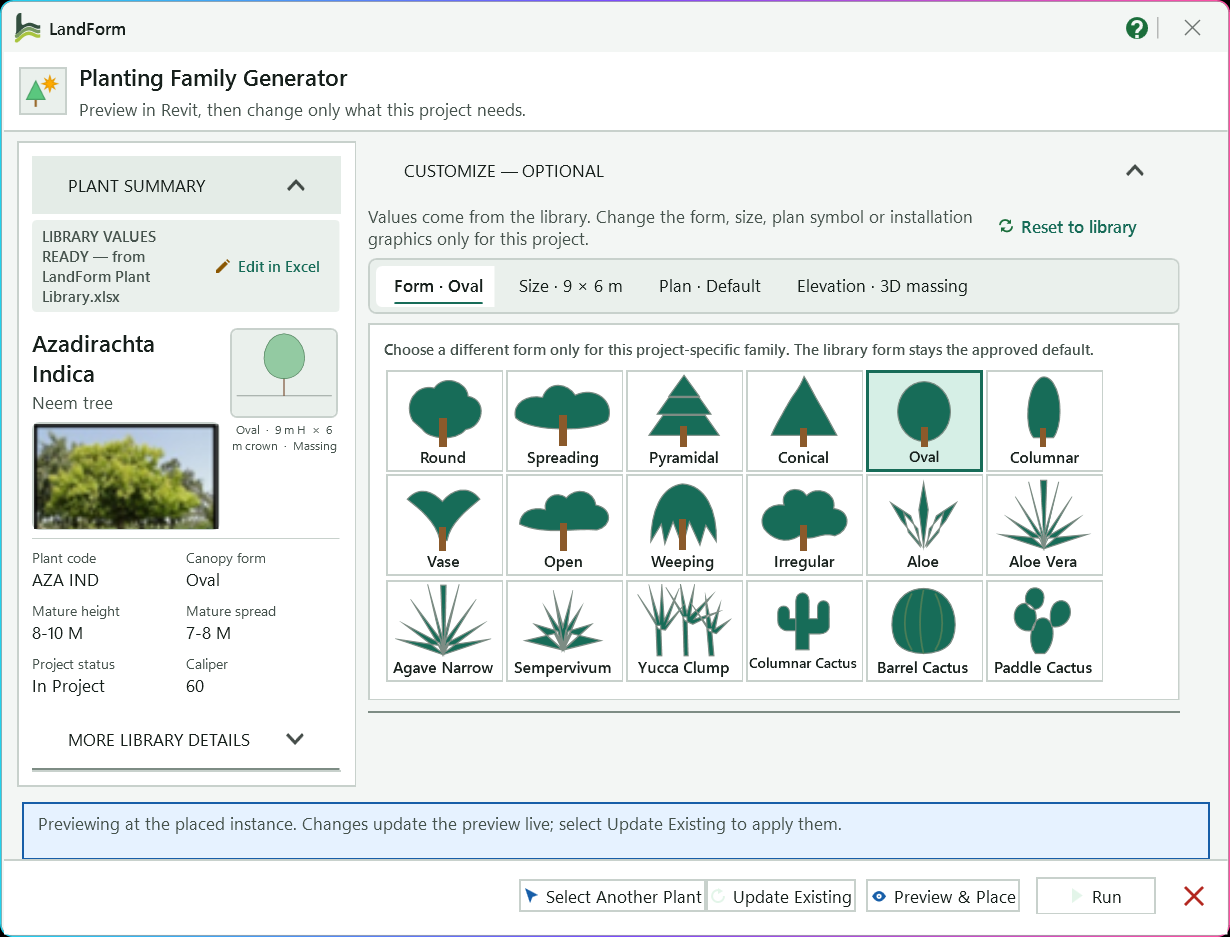
Botanical and common name, photo, current symbol, plant code, canopy form, mature size, project status and caliper.
Expands the specification, suitability and remarks from the library.
The form tab; its label shows the current form.
Pick another silhouette; a form that differs from the library asks you to confirm the project exception.
Height, crown, clear trunk and trunk diameter, plus the clear zone, rootball and staking graphics.
Chooses the plan symbol, filtered by plant group and scaled to the crown.
Chooses the outline drawn in elevations and sections.
Confirms the live preview at the placed plant and reports any automatic size adjustment.
Moves the live preview to a point you pick in the view.
Restores the approved library values and clears your overrides.
Regenerates and reloads the family; every instance updates and keeps its location.
Closes the editor so you can pick the next library plant in the model.
Updates the family like Update Existing and places one more instance at the preview point.
Opens the plant's row in a company library workbook to change its approved values; the bundled catalog is read-only.
Open LandForm tab → Softscape panel → Planting ▾ → Planting Editor.
Choose the plant. Select a library planting instance in the view, then start Planting Editor. With nothing selected, the tool asks you to pick one.
Check the summary. The Plant Summary panel shows the botanical and common name, plant code, canopy form, mature height and spread, caliper and, under More library details, the specification, suitability and remarks from the library. The editor starts from the values stored with the family.
Change the form (optional). On the Form tab, pick another silhouette such as Round, Columnar, Weeping or one of the succulent and cactus forms. If it differs from the library form, LandForm asks you to confirm the project exception first.
Change the size and installation graphics. On the Size tab, edit Height (m), Crown Ø (m), Clear trunk (m) and Trunk Ø (m). Tick Clear zone, Rootball and Staking to draw those graphics with the family, and choose Clear zone shape: Default (bowl) uses Clear zone Ø, Cube asks for Depth, Length and Width, and Cylinder asks for the diameter and Depth.
Change the symbols (optional). On the Plan symbol tab, choose the plan symbol, filtered by All, Trees, Palms or Grasses; symbols scale to the crown diameter. On the Elevation tab, choose the outline drawn in elevations and sections.
Watch the preview. Every change redraws the preview at the plant's location in the active view. Press Preview & Place to move the preview to another point if you want to judge it elsewhere. Press Reset to library to go back to the approved library values.
Update. Press Update Existing. LandForm regenerates the family, reloads it into the project and reports that existing instances were updated.
Edit another plant or close. Press Select Another Plant to close the editor and pick the next library plant in the model, or close the window to finish. The plant you edited reappears in the view.
The planting family is rebuilt with your values and reloaded into the project in one undo step named "LF-Planting Family Generator: Load Family". Every instance of that family, in every view, takes the new form, size and graphics, and keeps its own location. A new RFA file is saved to the planting library output folder, in a subfolder for your Revit version, and the values are stored with the family, so opening the editor on it again starts from your project exception.
| Control | Function |
|---|---|
| Plant Summary | Library name, photo, code, canopy form, mature size, project status and caliper for the plant being edited, with more library details on request. |
| Reset to library | Restores the approved library values for this plant and clears your overrides. |
| Form | Silhouettes for the 3D form. Hidden for plants whose shape comes from a fixed recipe. |
| Size | Height, crown diameter, clear trunk and trunk diameter, plus the Clear zone, Rootball and Staking graphics and the clear-zone shape and size. |
| Plan symbol | Plan symbol drawn in plan views, scaled to the crown diameter, with a filter by plant group. |
| Elevation | Outline drawn in elevations and sections in place of the 3D massing. |
| Select Another Plant | Closes the editor and lets you pick another placed library plant. |
| Update Existing | Regenerates and reloads the family; every instance updates and keeps its location. |
| Preview & Place | Moves the live preview to a point you pick in the view. |
| Run | Regenerates and reloads the family as shown, and places one more instance at the preview point. |
| Close | Closes the editor without applying further changes and shows the edited plant again. |
No separate LandForm window. This command runs directly from Revit selection and prompts; follow the workflow above and the messages shown beside the cursor or on Revit's status bar.

Softscape · Planting · Tree Survey
Tree Survey Import takes the schedule an arboricultural consultant delivers, whether a BS 5837 schedule (UK), an AS 4970 tree assessment (Australia), a council-format table (New Zealand), a plain point export or a bespoke layout, and turns each row into a tree in the project. You map the columns once, choose how the trees are located (grid coordinates, latitude and longitude, or the tree tags written on a CAD survey), and press Run. The tree constraints plan, retained and removed tree schedules and tags then all follow from the data, and a revised schedule updates the same trees instead of doubling them.
LandForm tab→Softscape panel→Planting ▾→Tree Survey
Button tooltip: “Import an arboricultural tree survey schedule as parametric survey trees.”Tree Survey Import walkthrough. Until it is published, the steps and the annotated window below walk through the same workflow.
Numbers on the screenshot match the legend. Hover a number or a legend row to highlight the other.

Choose the .xlsx, .xlsm or .csv schedule to read.
Picks the right sheet when the workbook has several.
The built-in column layout; it switches by itself to the one whose column names match.
Opens the Column Mapping panel for columns, units, zone rule and tree style.
How the trees are located: shared survey grid, Project Base Point, internal origin, latitude and longitude, or CAD text.
The level the trees are hosted on.
Places or updates every tree, then selects and zooms to them.
Saves LandForm's schedule workbook with example sheets for each region.
Gives the next step, then rows read and the totals placed, updated and not located.
Open LandForm tab → Softscape panel → Planting ▾ → Tree Survey.
Open the survey. Press Open Survey and choose the file. The status line reports how many rows were read and on which row the headers were found. If the workbook has several sheets, pick the right one in Sheet.
Check the profile. Profile switches by itself to the built-in layout whose column names match: UK — BS 5837, AU — AS 4970, NZ — council schedule or Simple points (Code, Name, X, Y, Z). Anything the profile does not cover is guessed from the header text. The count beside Run shows how many trees were recognised.
Review the mapping. Press Map to open the Column Mapping panel. For each LandForm field, such as Tree ID, Species, Height, Trunk diameter, Crown spread or Easting / X, choose the spreadsheet column it reads from and the unit (mm, cm, m, ft or in). For a single Crown spread column, say whether it holds a Diameter or a Radius. The line under the list previews the first tree and any warnings.
Set the rules. In the same panel, choose the Zone rule used when the schedule has no RPA or TPZ column, how four Crown radii combine (Average or Maximum), and what Trees look like: Planting Library forms or Massing (fast). Leave Update existing by Tree ID and Phase existing / removed ticked unless you want otherwise.
Choose how trees are located. Pick the Coordinates option that matches the schedule (see Coordinate options below). For Match CAD text, press Pick CAD and click the survey drawing; the button then shows how many text labels were read.
Pick the level. Choose the Level the trees are hosted on. Trees without a ground level column sit on this level.
Run. Press Run. LandForm prepares the tree families, places or updates every tree, then selects and zooms to them. The status line gives the totals placed, updated, marked for removal and not located, and the first warning.
Save the profile (optional). If you changed the mapping for a consultant's own layout, type a name next to Save Profile and press it, so their next schedule maps itself.
Every located tree is now a family instance on the chosen level, carrying the survey values as instance parameters. With Planting Library forms, each species and size gets its own generated planting family, and a separate LF Survey Zone instance on the Site category draws its protection zone; with Massing (fast), every tree is an instance of the single parametric LF Survey Tree family, which draws its own zone. All placements are one undo step named "LF-Tree Survey: Import Survey Trees". When phasing is on, trees are created in the project's first phase and removed trees are demolished in the active view's phase, so Existing, Demolition and Proposed views show the right trees without filters.
Press Template to save LandForm's schedule workbook, Tree-Survey-Template.xlsx, wherever you like; it then opens in the tool so you can see the mapping against real rows. The workbook holds a Read me sheet, complete example sheets for the UK BS5837, AU AS4970 and NZ layouts, a Simple XYZ sheet for total-station or GIS point exports (Code, Name, X, Y, Z), and a Field Map that explains every column. Hand it to the arborist, or paste an existing survey into the sheet for your region: the built-in profiles map its headers without any setup.
| Option | What the X, Y and Z columns mean |
|---|---|
| Survey coordinates (shared) | Grid coordinates (OS, MGA, NZTM or a site grid) matched to the project's shared coordinates. If the project has no shared coordinates yet and the trees would land far from the origin, LandForm sets the Survey Point to the schedule's grid, rounded down to 100 m, and says so in the run summary. A project already on a different grid is refused with the fix spelled out. |
| Project Base Point | Values measured from the Project Base Point, as Revit spot coordinates report in Project mode. |
| Internal origin | Raw Revit internal coordinates. Values far from the origin are offset by their rounded centre instead, leaving shared coordinates unchanged. |
| Latitude / Longitude (WGS84) | Degrees, placed against the project's Site Location. Map Longitude to Easting / X and Latitude to Northing / Y. |
| Match CAD text | Each tree goes where its Tree ID is written as text in the picked CAD drawing. |
A mapped Z column (ground level) is used when present and read in the same system; otherwise trees sit on the chosen level.
LF_Tree Height, LF_Tree Canopy Diameter, LF_Tree Trunk Diameter, LF_Tree Protection Radius and LF_Tree Structural Radius hold the sizes, and in the LF Survey Tree family they drive the geometry.LF_Tree ID, LF_Tree Species, LF_Tree Common Name, LF_Tree Category, LF_Tree Retention, LF_Tree Condition, LF_Tree Structure, LF_Tree Age Class, LF_Tree Notes and LF_Tree Survey Source (the file name) carry the schedule text. They are shared parameters bound to Planting and Site instances, so they tag and schedule, and can be used on your own planting families.LF_Tree Retention reads Remove when the action column contains words such as *remove* or *fell*, or when the BS 5837 category is U; otherwise Retain.LF-SURVEY plus the species and size, with heights and spreads rounded to 0.5 m. Palms get fronds, conifers taper and broad species such as oaks spread; a re-import at the same size reuses the family.Tree Survey Profiles folder of LandForm's data folder in your user profile. Copy the file to a colleague and the same consultant's layout maps itself on their machine.LF_Tree ID are moved, retyped and updated instead of duplicated.170 + 190 are combined into the BS 5837 equivalent single stem, the square root of the sum of the squares.%TEMP%\LandForm\TreeSurvey-warnings.log; the status line shows the first one.T12 in the schedule matches T12, T 12 or 12 on the drawing.No separate LandForm window. This command runs directly from Revit selection and prompts; follow the workflow above and the messages shown beside the cursor or on Revit's status bar.

Softscape · Mixes · Mix Studio
Mix Studio is the planting workspace for optioneering. You pick the area, and the studio draws the mix straight away as coloured canopy circles and boulder outlines on a plan. Change the spacing, pattern or randomness and the plan follows; press Shuffle layout for another arrangement and Keep this option on the ones worth comparing. You can also build or edit the mix itself in the studio, and move, rotate, group and lock boulders by hand before you place anything.
The chosen layout becomes real planting family instances dropped onto the surface below each point, carrying the same Plant Mix data the tags, schedules and Mix Inventory read.
LandForm tab→Softscape panel→Mixes ▾→Mix Studio
Button tooltip: “Lay out a plant mix on one area and compare options before placing.”Mix Studio walkthrough. Until it is published, the steps and the annotated window below walk through the same workflow.
Numbers on the screenshot match the legend. Hover a number or a legend row to highlight the other.
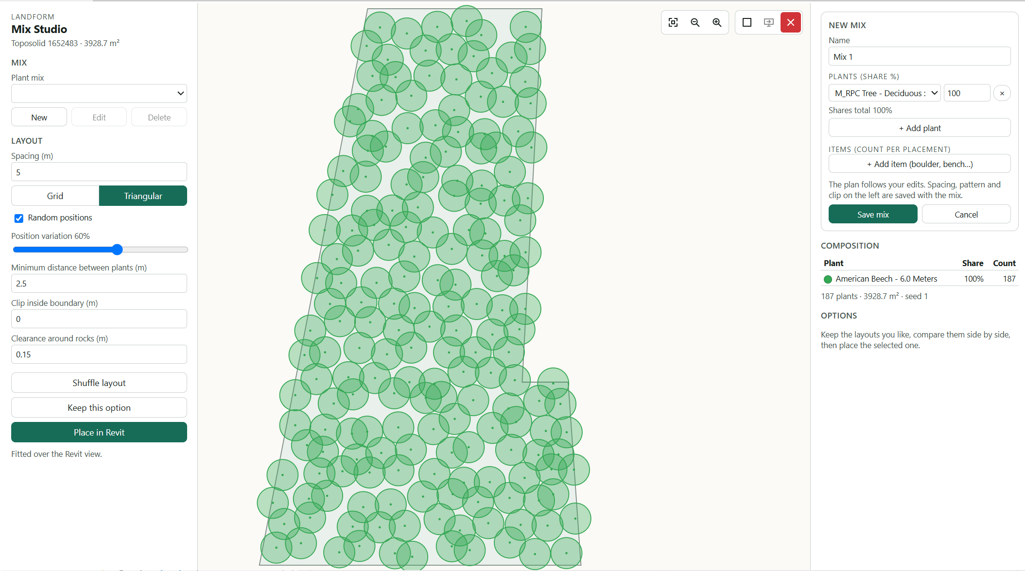
The picked area's name and its size in m².
Chooses the mix to lay out; the plan draws every plant as a canopy circle sized from its family.
Lists each plant's share and count in the current layout.
New and Edit open the mix editor on the right; Delete removes the selected mix from the project after you confirm.
Name the mix, add plants and their share in % with + Add plant, and counted items with + Add item. Save mix stores it in the project, Cancel drops the edits.
Sets the distance between plants and the planting pattern.
Gives a natural look and sets how far plants wander from the pattern.
Stops two plants landing too close together.
Keeps planting back from the edge and adds a gap between boulders and the plants beside them.
Shuffle layout makes a new random arrangement; Keep this option adds the current layout to Options.
The kept layouts: rename one, click it to show it again, or discard it with ×.
Shows the mix as canopy circles. Click, Shift+click and drag boulders to move them; scroll to zoom and drag empty space to pan.
Fits the area to the plan and zooms out or in.
Places the showing layout as planting family instances on the surface; the status line below reports how many elements were placed.
Open LandForm tab → Softscape panel → Mixes ▾ → Mix Studio.
Select the area. Select the planting area and start Mix Studio, or start it with nothing selected and pick one or more areas, then click Finish. The studio opens with the area name and its size in m² at the top left.
To change a mix that is already placed, select one of its plants instead; see "Updating a placed mix" below.
Choose the mix. Pick it in Plant mix. The plan draws every plant as a canopy circle sized from its family, and the Composition table on the right lists each plant's share and count.
Build or edit a mix (optional). Press New or Edit to open the mix editor on the right. Give it a Name, add rows with + Add plant (a family type and its share in %) and + Add item (boulder, bench…) (a family type and how many per placement). The plan follows every change. Press Save mix to store it in the project, or Cancel to drop the edits.
Shares that do not add up to 100% are saved scaled to 100%. Delete removes the selected mix from the project after you confirm; planting already placed stays.
Set the layout. Enter Spacing (m) and choose Grid or Triangular. Leave Random positions on for a natural look and set how far plants wander with Position variation; Minimum distance between plants (m) stops two plants landing too close. Clip inside boundary (m) keeps planting back from the edge, and Clearance around rocks (m) adds a gap between boulders and the plants beside them.
Shuffle and keep options. Press Shuffle layout for a new random arrangement; the badge at the top of the plan shows the layout number. Press Keep this option to add the current layout to Options, where you can rename it, click it to show it again, or discard it with ×.
Adjust boulders and plants by hand. Click a boulder to select it with its group, Shift+click to add more, and drag to move them; the plants re-settle around the boulders. Drag the rotate handle or use the 15° buttons to turn the selection. See "Editing boulders on the plan" below.
Place. Select the option you want (or leave the current layout showing) and press Place in Revit. The status line reports how many elements were placed and confirms the mix assembly.
Every plant and item of the layout is now a family instance in the model, dropped onto the surface below its point, with items turned to the rotation you gave them. Each picked area gets its own placement with its own Plant Mix assembly and tag, and the whole placement is one undo step named "LF-Mix Studio: Place Mix Layout". The planting carries the mix data, so tags, schedules and Mix Inventory pick it up like any other Plant Mix placement, and Mix Studio can reopen it later.
Select any plant of a placed mix and start Mix Studio. The studio opens that placement exactly as it stands: every plant keeps its species and every boulder is locked where it is. The area line reads "updating a placed mix" and the main button becomes Update in Revit. Move or delete plants and boulders, change the layout settings, or press Shuffle layout for a fresh arrangement, then press Update in Revit. The new instances are created first and the old ones are deleted only after that, in one step named "LF-Mix Studio: Update Mix Layout".
No separate LandForm window. This command runs directly from Revit selection and prompts; follow the workflow above and the messages shown beside the cursor or on Revit's status bar.
Softscape · Mixes · Apply Mix
Apply Mix is Mix Studio in a compact window, for when the mix is already decided and you just want it on the ground. You select the areas, choose the mix, glance at the plan and the plant counts, shuffle if the arrangement does not suit, and place. There are no layout fields to fill in: the spacing, pattern, randomness and boundary clip come from the mix itself.
LandForm tab→Softscape panel→Mixes ▾→Apply Mix
Button tooltip: “Apply a plant mix to one or more areas in a few clicks.”Apply Mix walkthrough. Until it is published, the steps and the annotated window below walk through the same workflow.
Numbers on the screenshot match the legend. Hover a number or a legend row to highlight the other.
The picked area's name and its total size in m².
Chooses the saved mix to place; the line beneath it then lists the plant counts and total area.
Draws the area outline, with every plant as a canopy circle and every boulder or item as an outline.
Makes a new random arrangement until the planting reads well.
Places the mix on each picked area, each with its own Plant Mix assembly and tag.
Reports how many elements were placed.
Fits the area in the plan and zooms in and out.
Open LandForm tab → Softscape panel → Mixes ▾ → Apply Mix.
Select the areas. Select the planting areas and start Apply Mix, or start it with nothing selected, pick the areas and click Finish. The window opens with the area name and its total size in m².
Choose the mix. Pick it in Plant mix. The plan draws every plant as a canopy circle and every boulder or item as an outline, and the line beneath the selector lists how many of each plant will be placed, followed by the total area.
Shuffle if needed. Press Shuffle layout for a new random arrangement until the planting reads well. The badge at the top of the plan shows the layout number.
Place. Press Place in Revit. The status line reports how many elements were placed and, when you picked several areas, that each area got its own assembly.
Refine later (optional). To change one of the placements, select any of its plants and start Mix Studio, which reopens that placement with the full set of layout, option and boulder controls.
The mix is now placed as family instances dropped onto the surface below each point. Every picked area is its own placement with its own Plant Mix assembly and tag, so tags, schedules and Mix Inventory report the areas separately. The whole placement is one undo step named "LF-Mix Studio: Place Mix Layout".
No separate LandForm window. This command runs directly from Revit selection and prompts; follow the workflow above and the messages shown beside the cursor or on Revit's status bar.

Softscape · Mixes · Planting Zones
Drawing drifts by hand means sketching dozens of split lines across a bed and then deciding, zone by zone, what goes where. Planting Zones does the linework for you. It draws the pattern over your beds (long sweeping lines with cross cuts that stop on them, the way parcel linework is drawn, or drifts, ribbons, waves, bands and grids), shares the ground between tall shrubs, shrubs and groundcover by plant count and height, and gives neighbouring zones different types. You shuffle until a layout reads well, steer it with a stroke or a split of your own, and create it in one step.
LandForm tab→Softscape panel→Mixes ▾→Planting Zones
Button tooltip: “Split planting beds into planting zones by pattern and planting hierarchy.”Planting Zones walkthrough. Until it is published, the steps and the annotated window below walk through the same workflow.
Numbers on the screenshot match the legend. Hover a number or a legend row to highlight the other.
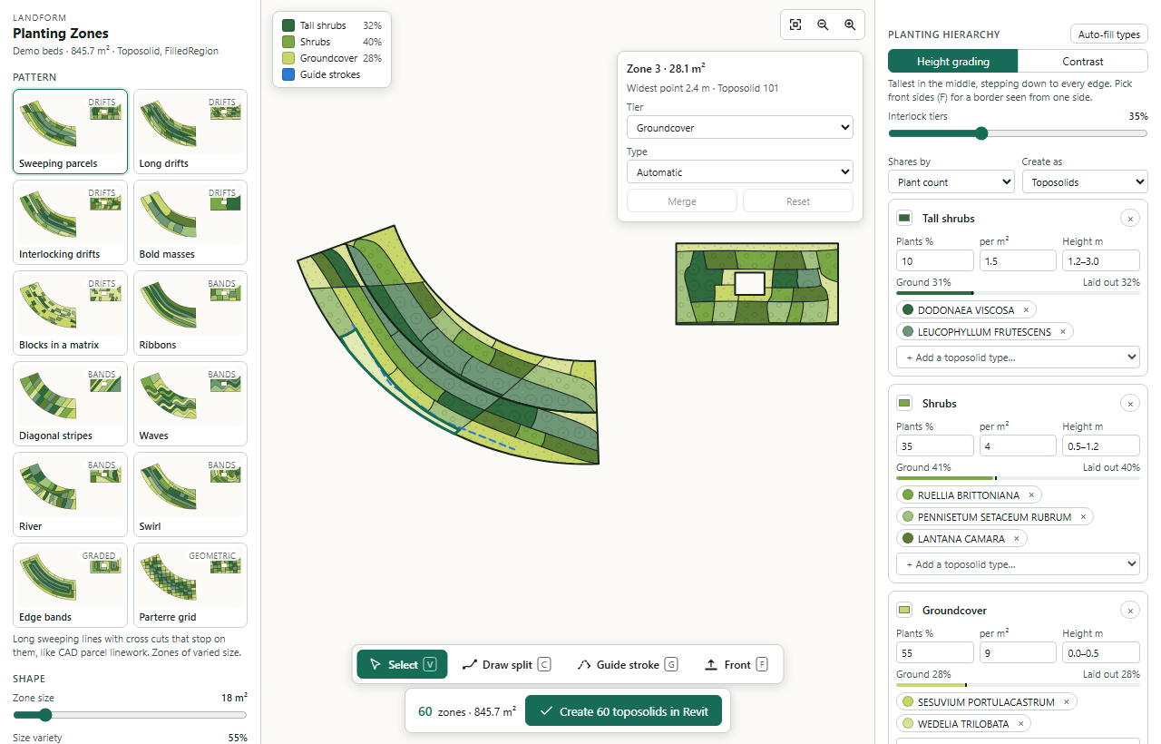
Twelve patterns, each drawn on your own beds. Click one to lay it out.
The sliders the chosen pattern uses: zone size, size variety, stretch, organic, crossing lines, band width and so on.
The tiers with the share of the bed each one has, plus the front and guide strokes when you add them.
The zones, filled with each zone's type colour and a texture per tier (canopies, shrubs, groundcover dots).
A dashed stroke you dragged; the lines near it follow its direction.
Size, widest point and bed of the zone you clicked; change its tier or type, or Merge several.
Fits the beds and zooms in and out.
How the tiers are arranged over the bed.
Puts the project's planting types into the tiers by mature height.
Toposolids or floors.
Plants %, plants per m² and height range, the ground the tier needs against what was laid out, and its types.
Select, Draw split, Guide stroke and Front.
The zone count and area, and the button that creates the zones in Revit.
Open LandForm tab → Softscape panel → Mixes ▾ → Planting Zones.
Select the beds. Select the floors, toposolids or filled regions and start Planting Zones (Softscape › Mixes), or start it with nothing selected, pick the beds and click Finish. The window opens over the view with every bed drawn and a first layout.
Pick a pattern. Click a card in the gallery. Shuffle (or ◀ ▶) gives another layout with the same settings; the number is the layout's seed.
Shape it. Move the sliders under Shape. Zone size is the area the zones aim for (a garden drift of 5 to 20 plants is about 1 to 3 m², a park mass of 20 to 100 plants about 3 to 15 m²). Size variety mixes small and large zones, Stretch makes them long and narrow, Organic makes the lines wander and the cuts bow. Min width joins zones too narrow to plant to a neighbour; Edge band adds a band of the lowest tier along the edge.
Steer it (optional). Press Guide stroke (G) and drag along the direction the lines should run. Press Draw split (C) and click points to draw your own split; double-click or Enter ends it, and an end that stops short runs on to the next line. Smooth on the draw card makes the new split a curve through its points, off makes it straight lines. Press Front (F) and click the sides people see a bed from: its tall plants move to the back and its bands run parallel to the front.
- Reshape a split. A split stays selected after you draw it, and in Select mode a click on any split selects it again. Drag its square grips to move points, the round grip in the middle of a segment to bow it into an arc (drag it back onto the line to straighten it), or drag the line itself to move the whole split. The card above the plan sets the clicked segment to Straight, Arc or Smooth (Shift for every segment of the split); a smooth segment shows tangent grips you drag to shape it, and Alt while dragging breaks the tangent for a corner. Double-click the line to add a point, double-click a point to remove it, Delete removes the point or the split.
Set the tiers. Click Auto-fill types, or add types to each tier with + Add a toposolid type…. Each tier has a share by plant count and a planting density; the bar shows the ground the tier needs against what was laid out. Choose Height grading (tall in the middle, or at the back when a front is picked) or Contrast (neighbouring zones differ, tall zones spread out).
Edit zones (optional). In Select mode click a zone to see it; change its tier or type in the card. Shift-click several neighbouring zones and press Merge (M) to join them.
- Surface zones. Set a zone's tier to Surface (not planted) for gravel, soil, mulch, lawn or hardscape, then pick any toposolid or floor type of the project in Type. Surface zones take no plants and are listed apart in the legend and the summary; the tiers share the planted ground that is left. A floor type (paving) on a toposolid bed is laid over the bed as a floor when the zones are created, and the ground under it keeps the bed's type. - Match type. Press Match… in the zone card (or Match on the mode bar, T) and click the zones that should get the same tier and type, or the same surface; with no zone selected, the first click takes the source. Esc ends it. - Undo. Every edit in the studio (pattern, sliders, shuffle, splits, guide strokes, front sides, merges, zone tiers and types, the tiers themselves) can be undone and redone with the arrows at the left of the mode bar or Ctrl+Z / Ctrl+Y; the arrow's tooltip names the edit.
Compare. Press Keep this option to add the layout to Options; click an option to bring it back.
Create. Press Create … in Revit. Zones of a tier without a type keep the bed's own type, and you are asked first.
Every floor or toposolid you picked is split along the zones: each zone becomes its own element with the zone's type, and the element you picked keeps one of the zones. Zone outlines run along real arcs where the lines curve, and toposolids keep their shape points along the new edges, so sloped beds stay sloped. Filled regions stay as they are, with a new toposolid (or floor) per zone at their level. The whole creation is one undo step named "LF-Planting Zones: Create Zones".
No separate LandForm window. This command runs directly from Revit selection and prompts; follow the workflow above and the messages shown beside the cursor or on Revit's status bar.

Softscape · Mixes · Surface Mix
Surface Mix is for planting beds that are modelled as one toposolid but specified as a blend: 60 % of one groundcover, 40 % of another. You build a Type board of Toposolid types with target percentages, choose which existing type supplies the construction and graphics, and press Run. LandForm duplicates that base type under the mix name and writes the composition into three type parameters, so tags and schedules can read the mix without any manual typing. The mix definition is saved in the project, so you can reopen it, change a percentage and update the type later.
LandForm tab→Softscape panel→Mixes ▾→Surface Mix
Button tooltip: “Create and edit Toposolid Surface Mix types with tag-ready parameter data.”Surface Mix walkthrough. Until it is published, the steps and the annotated window below walk through the same workflow.
Numbers on the screenshot match the legend. Hover a number or a legend row to highlight the other.
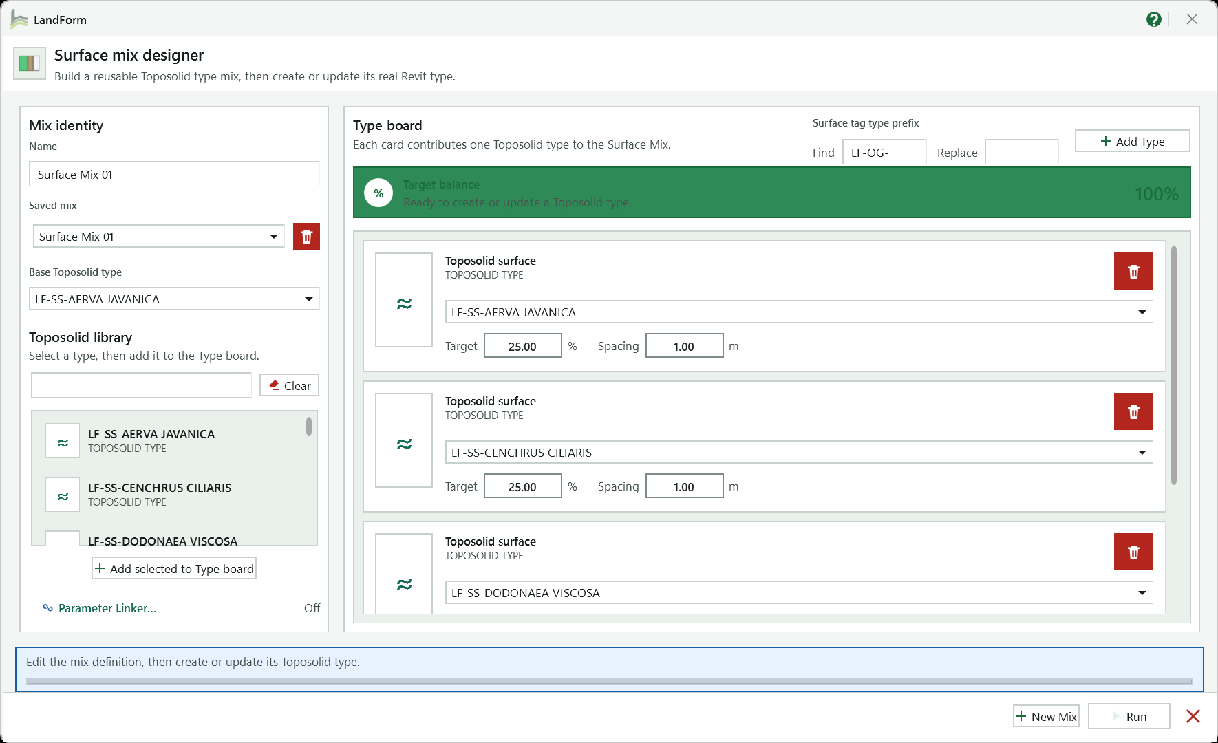
Starts a fresh draft named Surface Mix 01, 02 and so on; only one unsaved draft exists at a time.
Name of the mix, which becomes the name of the generated Toposolid type.
The type whose construction and graphics the new type duplicates.
Search by name (Clear empties the search), select a type and press Add selected to Type board, or double-click it.
Adds the next type not yet on the board as a new card; the targets rebalance evenly.
The card's type, its target share in per cent and a design spacing in metres. Picking a type already on the board merges the two cards.
Removes that type's card from the mix; the targets rebalance.
Running total of the targets, here 100% and ready; Run stays disabled until the mix is valid.
Find a prefix at the start of type names and Replace it in tag and schedule text; leave Replace blank to remove it. Revit type names are not changed.
Mirrors the mix name, contents and percentages into your own text type parameters; the summary beside it reads Off or the number of linked fields.
Saves the mix library and creates or updates the Toposolid type in one undo step.
Guidance and the result of the last action, such as the type just created.
Switches between the mixes in this project; the red button deletes the mix and its generated type after a Yes/No confirmation.
Open LandForm tab → Softscape panel → Mixes ▾ → Surface Mix.
Start or pick a mix. The window opens on the first saved mix. Press New Mix in the footer for a fresh draft (named "Surface Mix 01", "Surface Mix 02" and so on) and type its Name under Mix identity. The name becomes the name of the generated Toposolid type.
Only one unsaved draft exists at a time: if a draft is already waiting, New Mix selects it instead of making another.
Choose the base type. Under Base Toposolid type, pick the type whose construction and graphics the new type should duplicate. A new draft starts with the first available type here and on the board.
Fill the Type board. In Toposolid library, type part of a name to search, select a type and press Add selected to Type board (or double-click it). + Add type on the board adds the next type that is not yet used. Each type gets a card, and the targets are rebalanced evenly every time a card is added or removed.
Set the targets. On each card choose the Toposolid type, enter its Target share in per cent and a design Spacing in metres for that plant type. The Target balance panel shows the running total and what is missing ("Adjust targets by 10% to reach 100%"); Run stays disabled until the mix is valid, and hovering it shows the reason.
Picking a type that is already on the board merges the two cards into one and adds their targets together.
Link your own parameters (optional). Press Parameter Linker…, tick Enable Parameter Linker, map Mix name, Contents and Percentages to text type parameters from your project, then press Save links. The summary beside the button reads "Off" or "2 fields linked". While linking is on, LandForm manages those values and restores any manual edit from the mix.
Run. Press Run. The mix library is saved to the project and the Toposolid type is created, or updated if this mix already has one, in one undo step named "LF-Surface Mix: Create Mix Type". The status line confirms "Created Toposolid type 'LF Dry Garden Mix'. The editor remains open."
Reopen, update or delete. Use Saved mix to switch between mixes; every generated Surface Mix type is listed there. Edit the cards and press Run again to update the type, including a rename. The red delete button next to Saved mix removes the mix and its generated type after a Yes/No confirmation; it is refused while any Toposolid still uses the type.
The project now holds a Toposolid type named after the mix, duplicated from the base type, with three type parameters filled in: LF_Surface Mix (the mix name), LF_Surface Mix Contents (one line per component, such as "60% - Groundcover A @ 0.5 m") and LF_Surface Mix Percentages ("60%; 40%"). Assign it to toposolids like any other type; the recipe stays attached to the type however many toposolids use it. The window stays open so you can build the next mix, and Mix Inventory lists the type under Surface Mixes with its composition and the toposolids that use it.
| Control | Function |
|---|---|
| Enable Parameter Linker | Switches the mirroring on. With it off the three LandForm parameters are still written; only your own parameters stay untouched. |
| Mix name | Your text type parameter that should receive the mix name. |
| Contents | Your text type parameter for the composition lines. |
| Percentages | Your text type parameter for the percentage list. |
| Save links | Stores the mapping with the mix library. Two fields cannot share one target parameter. |
The Saved mix list: switches between the mixes stored in this project, including every generated Surface Mix type.
Name of the mix. It becomes the name of the generated Toposolid type and the value of LF_Surface Mix.
Opens the Parameter Linker, where the mix name, contents and percentages can be mirrored into your own text type parameters for tags and schedules.
Adds the next Toposolid type that is not yet on the Type board as a new card and rebalances the targets evenly.
The Toposolid type a card contributes to the mix. Choosing a type that is already on the board merges the two cards into one.
Target share of this type in per cent. All cards must total exactly 100 before Run is enabled.
Closes Surface Mix. Mixes saved by Run stay in the project.

Softscape · Palettes · Mix Inventory
Mix Inventory is the audit window for planting mixes. The Plant Mixes tab lists each mix with how many plants it has placed and breaks that down by family and type; the Surface Mixes tab lists each generated Toposolid type with the toposolids that use it and the recipe stored on the type. From either tab you can select the elements in Revit, zoom to them, or (for Plant Mixes) delete a whole placement cleanly, including its tags.
LandForm tab→Softscape panel→Palettes ▾→Mix Inventory
Button tooltip: “Inspect Plant Mix placements and Toposolid Surface Mix types.”Mix Inventory walkthrough. Until it is published, the steps and the annotated window below walk through the same workflow.
Numbers on the screenshot match the legend. Hover a number or a legend row to highlight the other.
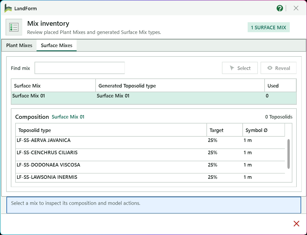
Switches between placed Plant Mixes and generated Surface Mix Toposolid types.
Counts the mixes on the open tab.
Filters the list by mix name, and here by generated Toposolid type name too.
The list of mixes with their generated Toposolid type and how many toposolids use it; click a row to load its composition.
Each Toposolid type in the selected mix with its target percentage and plan symbol diameter.
Makes every element of the chosen mix the current Revit selection.
Selects the elements and zooms the active view to them.
Tells you what to do next.
Returns to the model.
Open LandForm tab → Softscape panel → Palettes ▾ → Mix Inventory.
Pick the tab. Open Plant Mixes for placed planting or Surface Mixes for Toposolid types. The badge in the header shows the count, for example "3 PLANT MIXES".
Find the mix. Type in Find mix to filter the list by mix name (on the Surface Mixes tab the generated Toposolid type name is searched too). Click a row to load its Composition below: for a Plant Mix the family, type, placed count and share of each component; for a Surface Mix each Toposolid type with its target percentage and plan symbol diameter.
Select the elements. Press Select. Every placed instance of the Plant Mix, or every toposolid using the Surface Mix type, becomes the current Revit selection, so you can inspect, move or filter them.
Reveal them. Press Reveal to select the elements and zoom the active view to them. If the view cannot show them, the selection still applies.
Delete a Plant Mix (optional). Press Delete on the Plant Mixes tab and confirm. LandForm removes the placed planting instances, deletes the Planting Palette tags that belong to the mix, resets the host overrides those tags applied, and removes the saved mix definition, in one undo step named "LF-Mix Inventory: Delete Mix". Family types stay loaded.
Close. Press the X in the footer to return to the model.
Nothing changes in the model unless you delete a mix: Mix Inventory is a reading tool whose Select and Reveal only set the Revit selection and view. After a delete, the mix's planting instances and tags are gone, its hosts show their normal graphics again, and the mix disappears from the list; the families and types it used remain in the project for other mixes.
Lists every Plant Mix placed in the project with its placed count and composition.
Filter by Plant Mix name.
Select: makes every placed instance of the chosen Plant Mix the current Revit selection.
Reveal: selects the mix's instances and zooms the active view to them.
Delete all placements belonging to the selected Plant Mix, with their Planting Palette tags, host overrides and saved definition; family types stay loaded.
The list of placed Plant Mixes: mix name and how many plants are placed.
Composition of the selected Plant Mix: family, type, placed count and share of the placed total.
Lists every Toposolid type generated by Surface Mix with its recipe and usage.
Filter by Surface Mix or generated Toposolid type name.
Select: makes every toposolid that uses the chosen Surface Mix type the current Revit selection.
Reveal: selects those toposolids and zooms the active view to them.
The list of Surface Mixes: mix name, generated Toposolid type and how many toposolids use it.
Composition stored on the selected type: each Toposolid type with its target percentage and plan symbol diameter.
Closes Mix Inventory.

Softscape · Palettes · Annotate Planting
Every mix placed by Mix Studio or Apply Mix is a Revit assembly carrying two parameters: LF_Planting Palette (the mix name) and LF_Planting Palette Contents (the actual percentages, planting type names and placed counts). Annotate Planting places Assembly Tags that display them, either on every assembly visible in the view at a fixed offset, or on one assembly at a point you click. Running it again moves and retypes the tags that already exist instead of adding duplicates, so the drawing stays tidy as the mixes change.
LandForm tab→Softscape panel→Palettes ▾→Annotate Planting
Button tooltip: “Tag Plant Mix assemblies in the active view.”LF_Planting Palette and LF_Planting Palette Contents.Annotate Planting walkthrough. Until it is published, the steps and the annotated window below walk through the same workflow.
Numbers on the screenshot match the legend. Hover a number or a legend row to highlight the other.
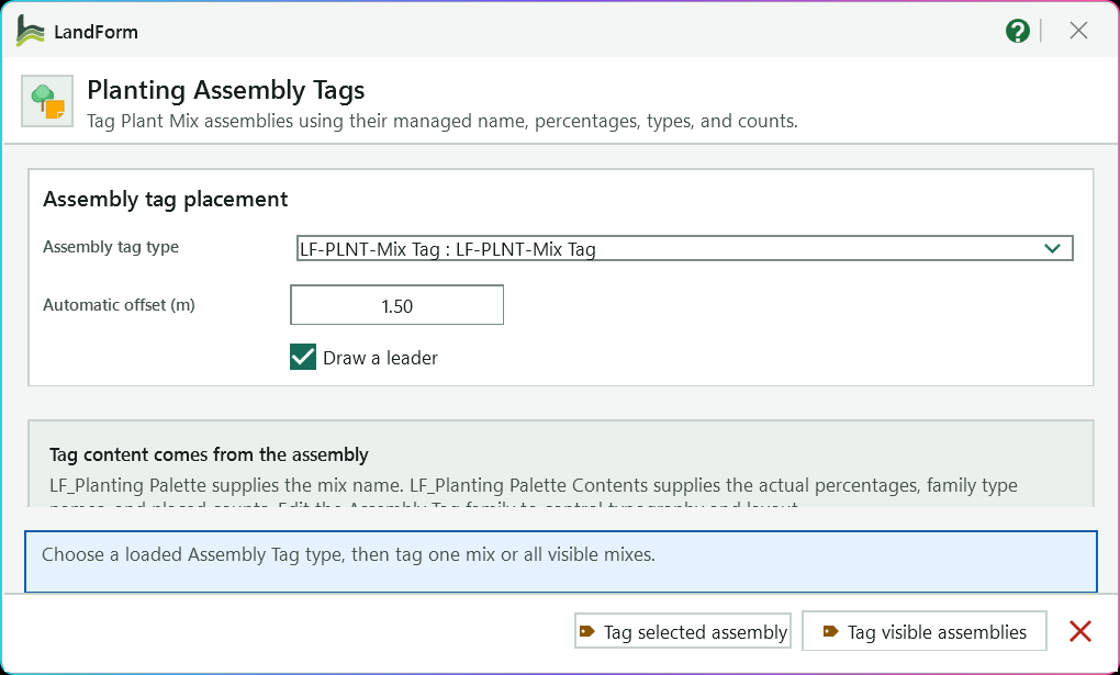
Chooses the loaded Assembly Tag type, listed as "Family : Type"; the bundled LF-PLNT-Mix Tag is selected on first use.
Distance from the centre of each assembly, along the view's up direction, where automatic tags are placed.
Gives every created or updated tag a leader line back to its assembly.
Reminds you that the tag text is read from LF_Planting Palette and LF_Planting Palette Contents; edit the tag family to change typography and layout.
Status line with the next step.
Tags every Plant Mix assembly visible in the active view at the offset, updating existing tags and removing legacy planting notes.
Hides the window so you can click one mix assembly and then where its tag head should go.
Closes the window when you have finished tagging.
Open LandForm tab → Softscape panel → Palettes ▾ → Annotate Planting.
Choose the tag type. Assembly tag type lists every loaded Assembly Tag type as "Family : Type". The bundled LF-PLNT-Mix Tag is selected on first use; afterwards the tool remembers your last choice.
Set the offset and leader. Enter Automatic offset (m), the distance from the centre of each assembly, measured in the view's up direction, where automatic tags are placed (1.5 m by default). Tick Draw a leader if the tags should point back at their assemblies.
Tag everything in the view. Press Tag visible assemblies. Every Plant Mix assembly visible in the active view receives a tag at the offset; assemblies that already have one keep it, moved to the new position and switched to the chosen type. Legacy planting text notes from earlier LandForm versions are removed at the same time. This is one undo step named "LF-Annotate Planting: Tag Mix Assemblies".
Or place one tag by hand. Press Tag selected assembly. The window hides while you click a Plant Mix assembly in the view and then click where the tag head should go. The step is named "LF-Annotate Planting: Tag Selected Mix Assembly".
Only LandForm mix assemblies can be picked; ordinary Revit assemblies are filtered out.
Read the summary. A dialog reports how many tags were created, how many updated and how many legacy notes were removed. The window stays open for the next view; close it with the X in the footer.
Each Plant Mix assembly in the view carries an Assembly Tag whose text comes live from the assembly's LF_Planting Palette and LF_Planting Palette Contents parameters, so when a mix is updated the tag follows without any retyping. Typography and layout belong to the tag family; edit the family to change them. Your tag type, leader and offset settings are saved on this computer for the next session.
LF_Planting Palette and LF_Planting Palette Contents, then run Annotate Planting again.The loaded Assembly Tag type used for new tags and applied to existing mix tags when they are updated. The bundled LF-PLNT-Mix Tag is the default.
Distance in metres from the assembly centre, along the view's up direction, where Tag visible assemblies places each tag head.
Gives every created or updated tag a leader line back to its assembly.
Hides the window, lets you click one Plant Mix assembly and then the tag position, and creates or updates that one tag.
Tags every Plant Mix assembly visible in the active view at the automatic offset, updating existing tags and removing legacy planting notes.

Softscape · Connector
Connector is the fast way to annotate a hedge, a row of trees or a drift of shrubs: instead of tagging each plant, you click along the run, LandForm collects every planting the route crosses, draws the connector as arcs or straight segments on its own line style, and places one planting tag with a leader at the point you choose. The tag references every planting in the run, and the connector remembers its settings so it can be updated later.
LandForm tab→Softscape panel→Connector
Button tooltip: “Create planting connector graphics and a tag.”Connector walkthrough. Until it is published, the steps and the annotated window below walk through the same workflow.
Numbers on the screenshot match the legend. Hover a number or a legend row to highlight the other.

The planting tag type placed at the end of the connector; the bundled LF-PLNT-Tag is the default.
Opens Normal Tag Settings to choose the planting parameter that receives the plant type name.
Offset of the connector arcs from the plantings, in metres.
Adds every matching planting each segment crosses; clear it to add only the planting nearest each click.
Starts the pick sequence at the first planting.
Tells you the next step and confirms when the connector is created.
While you draw: Tab changes the shape or leader, Backspace undoes a step, Esc finishes the route.
Open LandForm tab → Softscape panel → Connector.
Set the symbol and gap. Choose the tag type under Symbol, enter the Gap in metres and decide whether Auto nearby should sweep up every planting the route crosses.
Choose the label parameter (optional). Press the gear button to open Normal Tag Settings, pick the planting parameter under Write plant type name to, and press Run. LandForm writes each planting's type name into that parameter so the tag label can show it.
Press Create and pick the first planting. The toolbar hands over to Revit with the prompt "Pick the first planting for the LandForm connector". Click the plant where the run should start.
Draw the route. Click along the run. After each click, LandForm adds the plantings of the same type that the new segment crosses and redraws the preview. Press Tab to change the shape (arcs on the left, arcs alternating sides, arcs on the right, straight lines), Backspace or a click back on the last point to undo a step, and Esc when the route is complete.
Place the tag. Click the elbow of the 90° leader, then the tag location; or press Tab first to switch to a straight leader and click the tag location directly.
Let LandForm finish. The connector curves and the tag are created in one step named "LF-Plant Connector: Create and Style Connector", the curves are then moved to the LF-Plant Connector line style in a short second pass, and the status line reports "Connector created successfully." The toolbar stays open for the next run.
The view contains the connector as detail lines on the dedicated LF-Plant Connector line style, following the arcs or segments you drew at the gap you set, plus one planting tag attached to every planting in the run with the leader you placed. The chosen text parameter on each planting holds its type name, which is what the tag label displays. The tag stores the connector settings, so the Plant Connector update tools can redraw or restyle it later, and the selection is cleared ready for the next run.
The Planting Tag type (Family : Type) placed at the end of the connector; the bundled LF-PLNT-Tag is the default.
Opens Normal Tag Settings to choose the planting parameter that receives the plant type name shown by the tag label.
The Gap: offset of the connector arcs from the plantings, in metres. Must be greater than zero.
Include matching plantings crossed by each segment. Clear to use only the planting closest to each click and keep the click order.
Detail line style used by connector curves. Hidden in the current release: connectors always use the LF-Plant Connector style.
Shown only when the toolbar is opened on one existing connector tag. Pick the first planting, redraw the route, then press Update to apply it.
Create starts the pick sequence; it reads Update when editing an existing connector.
Closes the Connector toolbar.
Write plant type name to: the writable text parameter on each planting that receives its type name, so the tag label can display it.
Connector line thickness from 0.1 to 1.6 mm, matching Revit line weights 1 to 16. This override section is hidden in the current release.
Saves the settings for the next connector.
Text type used for a count-text connector label. The count-text mode is switched off in the current toolbar, so this window is not reachable from it.
Length of the text landing in metres for a count-text label.
Type-name prefixes to strip from count-text labels, one per line (commas and semicolons also work).
Saves the count-text settings.

Softscape · Plant Mix Schedule
The ribbon button is labelled Plant Mix Schedule. It has no window: press it and LandForm gathers every Plant Mix assembly created by Mix Studio or Apply Mix, writes the mix name and composition onto the planting it contains, and creates (or rebuilds) a planting schedule called LandForm - Plant Mix Schedule. Ordinary planting families and assemblies you made yourself are left out, so the schedule reads as a clean bill of mixes. If any mix includes counted site items such as boulders or benches, a second schedule, LandForm - Plant Mix Items, lists those per mix.
LandForm tab→Softscape panel→Plant Mix Schedule
Button tooltip: “Create or refresh the combined Plant Mix schedule.”Schedule walkthrough. Until it is published, the steps and the annotated window below walk through the same workflow.
Open LandForm tab → Softscape panel → Plant Mix Schedule.
Press Plant Mix Schedule. LandForm counts the mix assemblies in the project and binds the reporting parameters to the Planting category (and to the site-item categories) if they are not there yet.
Members are synchronised. Every planting inside a mix assembly receives the mix name in LF_Planting Palette, the combined composition text, and a grouping key in LF_Planting Mix Group that the schedule filters on. Site items in the mix receive the mix name and a LF_Planting Mix Item key.
The schedule is built. An existing "LandForm - Plant Mix Schedule" is reset and refilled; otherwise a new Planting schedule is created with the columns Mix, Composition and Plant Count, sorted by mix, not itemised, with a Grand Total row. The hidden group field keeps unrelated planting out. All of this is one undo step named "LF-Plant Mix Schedule: Create Schedule".
Items get their own schedule. When any mix carries counted items, "LandForm - Plant Mix Items" is created or refreshed as a multi-category schedule with Mix, Item and Count columns and its own grand total.
Read the confirmation. The schedule opens as the active view and a dialog reports how many LandForm mix assembly instances were scheduled and that unrelated assemblies were excluded.
Run again after changes. Place, update or delete mixes as the design develops, then press the button again; the same schedules are refreshed in place, so views placed on sheets keep working.
The Project Browser holds LandForm - Plant Mix Schedule under Schedules/Quantities, listing each mix once with its combined actual composition and the total number of plants, plus a grand total, and LandForm - Plant Mix Items when boulders or other counted items are part of a mix. The planting in each mix now carries LF_Planting Palette and the composition text as instance parameters, so your own tags and schedules can read them too.
No separate LandForm window. This command runs directly from Revit selection and prompts; follow the workflow above and the messages shown beside the cursor or on Revit's status bar.
LandForm ribbon panel
Dimensions, coordinates, tags and location maps for site drawings.

Annotation · Dims · 3D Dimension
3D Dimension is the quick check you reach for when Revit's own Measure tool is not enough: how far is it from the top of a wall to the kerb below, from a tree trunk to the edge of a toposolid, from one corner of a pergola to the opposite one? You click two points on surfaces, faces or edges, and LandForm reports the total distance together with its horizontal and vertical parts. Nothing in the model changes unless you choose to keep the guide.
LandForm tab→Annotation panel→Dims ▾→3D Dimension
Button tooltip: “Measure a true point-to-point distance in 3D.”3D Dimension walkthrough. Until it is published, the steps and the annotated window below walk through the same workflow.
Open LandForm tab → Annotation panel → Dims ▾ → 3D Dimension.
Pick the first point. Revit prompts you to pick the first 3D dimension point. Click a surface, face or edge. When you click close to the end of an edge, LandForm snaps to that corner so the measurement starts exactly at the vertex.
Pick the second point. A guide line now follows the cursor from the first point, so you can see the measurement before you commit. Click the second point on any surface, face or edge; it snaps to edge ends in the same way.
If the two points are almost the same place, LandForm asks you to pick two points that define a measurable distance and lets you pick again.
Read the result. A dialog headed "3D dimension measured." lists Distance (the straight line between the points), Horizontal (the plan distance) and Vertical (the level difference), all in metres to three decimals. The guide stays highlighted on screen while the dialog is open.
Decide what to do with the guide. Press Keep guide to write the measurement into the model as model lines, Measure another to discard it and pick a new pair of points, or Cancel to finish.
Repeat or finish. After Keep guide or Measure another the tool goes straight back to step 1. Press Esc during a pick to leave the tool.
If you only read the numbers, the model is untouched. Each time you press Keep guide, LandForm adds model lines for the measured line and a short tick mark at each end, sized to the view scale, in one undo step named "LF-3D Dimension: Keep Dimension Guide". The lines are ordinary model lines on their own sketch planes, so you can select, move or delete them like any other line.
No separate LandForm window. This command runs directly from Revit selection and prompts; follow the workflow above and the messages shown beside the cursor or on Revit's status bar.

Annotation · Dims · Z Dimension
Z Dimension answers the question "how much higher is that than this?" without the horizontal offset getting in the way. You pick a base point, then pick any point whose level you want to compare it with; LandForm takes only the elevation of that second pick and drops it onto the vertical line through the base point. The result is the level difference plus both elevations, and you can keep the vertical guide as model lines for later reference.
LandForm tab→Annotation panel→Dims ▾→Z Dimension
Button tooltip: “Measure vertical elevation difference while locking X/Y.”Z Dimension walkthrough. Until it is published, the steps and the annotated window below walk through the same workflow.
Open LandForm tab → Annotation panel → Dims ▾ → Z Dimension.
Pick the base point. Revit prompts you to pick the base point for the Z dimension. Click a surface, face or edge; a click near the end of an edge snaps to that corner. This point fixes the X and Y of the measurement.
Pick the elevation reference. Move the cursor and a live guide appears: a vertical line rising or falling from the base point, joined by a horizontal line to wherever the cursor is, so you can see which level is being read. Click the point whose elevation you want to compare. Only its height is used; its position in plan is ignored.
If the second point is at almost the same elevation as the base, LandForm asks you to pick two points that define a measurable distance and lets you pick again.
Read the result. A dialog headed "Z dimension measured." lists Z distance, Base elevation and Reference elevation, all in metres to three decimals.
Keep the guide or carry on. Press Keep guide to write the vertical line, the horizontal link to the reference point and the end ticks into the model as model lines; press Measure another to discard the guide and start a new measurement; press Cancel to finish.
Repeat or finish. After either Keep guide or Measure another the tool returns to step 1. Press Esc at a prompt to leave the tool.
Reading the numbers changes nothing in the model. Each Keep guide adds model lines for the vertical measurement, the horizontal line back to the point you clicked and a short tick at each end, sized to the view scale, in one undo step named "LF-Z Dimension: Keep Dimension Guide". The lines are plain model lines and can be moved or deleted like any other.
No separate LandForm window. This command runs directly from Revit selection and prompts; follow the workflow above and the messages shown beside the cursor or on Revit's status bar.

Annotation · Dims · Dimension By Line
Dimension By Line replaces the click-click-click of the standard Aligned Dimension tool. You press Dimension, click a start point, drag across the walls, lines, grids, columns or other elements you want measured, and click an end point. Every element the line cuts becomes a witness, LandForm orders and de-duplicates the crossings, and Revit creates a real dimension attached to real references, so it keeps updating when the model moves. The toolbar stays open so you can drag string after string until you press Esc.
LandForm tab→Annotation panel→Dims ▾→Dimension By Line
Button tooltip: “Dimension everything a dragged line crosses.”Dimension By Line walkthrough. Until it is published, the steps and the annotated window below walk through the same workflow.
Numbers on the screenshot match the legend. Hover a number or a legend row to highlight the other.

The string is squared to the first element it cuts, so rotated content dimensions cleanly.
Object snaps uses Revit's snapping while you pick; Off lands exactly where you click.
Adds an outer dimension from the first witness to the last.
Adds a third click to choose where the finished string sits.
Also measures elements inside loaded Revit links.
Opens the What to measure panel: the categories the line picks up and whether each is read at its edges or centre.
Starts the line: click a start point, drag across the elements and click an end point.
Guides each pick and reports how many witnesses each new dimension got.
Open LandForm tab → Annotation panel → Dims ▾ → Dimension By Line.
Check the toolbar settings. Direction shows how the string is squared: the dimension line turns to sit square to the first element it cuts, so rotated content dimensions as cleanly as orthogonal content. Set Snap to Object snaps to use Revit's snapping while you pick, or Off to land exactly where you click. Leave Overall on to add an outer dimension from the first witness to the last, tick Pick placement to choose where the string sits with a third click, and tick Links to measure elements inside loaded Revit links as well.
Choose what is measured (optional). Press Setup to open the What to measure panel. Tick the categories the line may pick up and, for each, choose Edges, Centre or Edges + centre; categories with only one way to be measured show a greyed-out choice. All ticks every category, None clears them and Defaults restores the shipped settings. Press Setup again to hide the panel.
Every change is saved immediately and remembered the next time you open the tool.
Start the line. Press Dimension. The status line asks you to drag a dimension line across what you want dimensioned; click the start point.
Drag across the elements. As you move the cursor, the line follows it and a small cross marks every reference the line is picking up, so you can see which witnesses you will get before you commit. Click the end point.
In a very heavy view the live crosses may pause so the pick stays smooth; the crossings are still found when you click.
Place the string (optional). With Pick placement on, the finished dimension line follows the cursor while the crosses stay on the elements. Click where the string should sit, clear of the geometry.
Read the status and continue. The status line reports "Created dimension 1 across N witness(es)", adding "plus an overall dimension" when Overall applied. Drag the next line straight away, or press Esc to finish; the final message counts the dimensions you created.
Each drag leaves a native Revit dimension in the active view whose witnesses are attached to the faces, centrelines, grids or lines the dragged line crossed, in one undo step named "LF-Dimension By Line: Create Dimensions". With Overall on and more than two witnesses, a second dimension spanning the first and last witness sits about 10 mm (on paper) outboard of the string, on the side away from the measured geometry. Because the references are real, the dimensions move and re-read when the model changes, exactly like dimensions you place by hand.
| Categories | Measured at | On by default |
|---|---|---|
| Model lines, Detail lines, Room separation lines, Reference lines, Curtain grid lines | Centre only (the line itself) | Model lines, Detail lines |
| Grids, Reference planes, Levels | Centre only (the datum) | Grids |
| Trusses | Centre only | none |
| Walls, Columns, Structural columns, Structural framing, Structural foundations, Floors, Roofs, Ceilings, Railings, Casework, Generic models, Mechanical equipment, Air terminals, Curtain panels, Curtain wall mullions, Parts | Edges, Centre or Edges + centre (start at Edges) | Walls, Columns, Structural columns |
| Doors, Windows, Ducts, Round ducts, Pipes, Cable trays, Conduits | Edges, Centre or Edges + centre (start at Edges + centre) | none |
| Structural rebar | Edges, Centre or Edges + centre (starts at Centre) | none |
| Curtain walls, Foundation slabs, Ramps, Area reinforcement, Path reinforcement, Pipe insulations, Duct insulations | Edges only | none |
No separate LandForm window. This command runs directly from Revit selection and prompts; follow the workflow above and the messages shown beside the cursor or on Revit's status bar.

Annotation · Dims · Live Coordinates
Live Coordinates is how you get setting-out data onto trees, lights, bollards, boulders and other placed families without typing a single number. Pick the model categories, decide whether the values should be shared (survey) coordinates, project coordinates or Revit's internal origin, and press Run. LandForm writes the values into instance parameters, creating and binding its own LF_X, LF_Y and LF_Z parameters if you ask it to, and registers an updater so that dragging an instance rewrites its coordinates straight away.
LandForm tab→Annotation panel→Dims ▾→Live Coordinates
Button tooltip: “Write and maintain live coordinates on family instances.”Live Coordinates walkthrough. Until it is published, the steps and the annotated window below walk through the same workflow.
Numbers on the screenshot match the legend. Hover a number or a legend row to highlight the other.
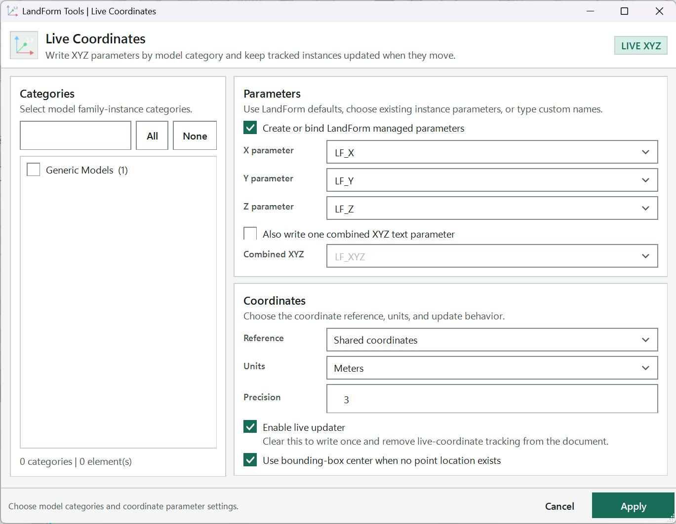
Type part of a category name to shorten the list.
Tick or clear every category currently shown.
Tick each category whose instances receive coordinates; the number in brackets is how many instances the model holds.
Counts the ticked categories and their instances.
Creates LandForm's shared text parameters and binds them to the ticked categories; clear it to write into existing instance parameters.
Parameters that receive the X, Y and Z values; keep LF_X, LF_Y and LF_Z or pick or type other names.
Also writes one text value with all three coordinates, handy for a one-line tag.
Parameter that receives the combined text, LF_XYZ by default.
Shared coordinates for survey Easting and Northing, Project coordinates from the Project Base Point, or Internal origin.
Meters, Feet or Internal feet. Scroll down for Precision and the live updater options.
Tells you what to set next.
Binds any managed parameters, writes the coordinates and reports how many elements were updated.
Open LandForm tab → Annotation panel → Dims ▾ → Live Coordinates.
Tick the categories. In the Categories panel, tick each category whose instances should receive coordinates. Type in the filter box to shorten the list, and use All or None to tick or clear every row currently shown. The line beneath the list counts the categories and instances you have selected.
On the first run Planting is ticked for you; if you had elements selected when you opened the tool, their categories are ticked instead, and on later runs your previous choice is restored.
Choose the parameters. Leave Create or bind LandForm managed parameters ticked and LandForm will create its shared text parameters and bind them as instance parameters (in the Data group) to the ticked categories before writing, so nothing has to exist in the families beforehand. Keep the defaults LF_X, LF_Y and LF_Z in X parameter, Y parameter and Z parameter, or type different names.
Clear the checkbox to write into existing instance parameters instead: pick them from the drop-down lists, which offer every parameter found on the eligible families.
Add a combined value (optional). Tick Also write one combined XYZ text parameter to also write a single text such as X=512.345 m, Y=1203.210 m, Z=14.250 m into the Combined XYZ parameter (LF_XYZ by default). This is handy for a one-line tag.
Set reference, units and precision. In the Coordinates panel choose the Reference system, the Units (Meters, Feet or Internal feet) and the Precision, the number of decimal places from 0 to 8 used for text values.
Decide on live updating. Leave Enable live updater ticked to keep the values synchronised whenever a tracked instance moves. Clear it to write the values once and remove live-coordinate tracking from every element in the document.
Leave Use bounding-box center when no point location exists ticked so families without an insertion point are measured at the centre of their extents instead of being skipped. Line-based families are measured at the midpoint of their line.
Run. Press Run. LandForm binds any managed parameters, writes the coordinates to every instance in the ticked categories and reports how many elements were updated, how many categories are enabled, and any instances it had to skip.
Every family instance in the ticked categories now carries its coordinates in the chosen parameters, formatted to the precision you set, ready for tags and schedules. With the updater enabled, each instance is tagged as tracked and LandForm rewrites its values the moment it is moved, in an undo step named "LF-Live Coordinates: Update Coordinates". The run itself is one undo step named "LF-Live Coordinates: Apply Coordinates", and the closing dialog reads "Live coordinates enabled." or, with the updater off, "Live coordinates updated once."
Type part of a category name to shorten the list. All and None act only on the rows that remain visible.
Ticks every category currently shown in the list.
Clears every category currently shown in the list.
The tick in front of each category row. Instances of ticked categories receive coordinates and, with the updater on, are tracked. The number in brackets is how many instances the model contains.
Creates LandForm's shared text parameters (LF_X, LF_Y, LF_Z and, when used, LF_XYZ) and binds them as instance parameters in the Data group to the ticked categories before writing. Clear it to write into instance parameters the families already have.
Parameter that receives the X value (Easting in shared coordinates). Pick an existing instance parameter or type a name; LF_X is the managed default.
Parameter that receives the Y value (Northing in shared coordinates). Pick an existing instance parameter or type a name; LF_Y is the managed default.
Parameter that receives the Z value (elevation). Pick an existing instance parameter or type a name; LF_Z is the managed default.
Also writes a single text value such as "X=512.345 m, Y=1203.210 m, Z=14.250 m" into the Combined XYZ parameter.
Text parameter that receives the combined value; LF_XYZ is the managed default. Enabled only while the combined option is ticked.
Shared coordinates reports survey Easting, Northing and elevation; Project coordinates measures from the Project Base Point; Internal origin uses Revit's internal coordinates.
Meters converts the values to metres; Feet and Internal feet write the values in feet.
Number of decimal places from 0 to 8 used when the value is written as text.
Registers the LandForm updater so tracked instances are rewritten whenever they move. Clear it to write once and remove live-coordinate tracking from every element in the document.
Measures families that have no insertion point and are not line-based at the centre of their bounding box instead of skipping them.
Binds parameters if asked, writes the coordinates to every instance in the ticked categories, applies the updater setting and reports the counts.
Closes the window without writing anything.

Annotation · Dims · Boundary Coordinates
Use Boundary Coordinates when a setting-out plan needs a point table: paving edges, platform corners, planting bed outlines. LandForm reads the top boundary of each selected surface, including any openings, removes corners that two surfaces share, and places one annotation marker per point in the active view. Each marker carries its number and its shared-coordinate Easting and Northing in metres, and LandForm can build the note block that lists them on a sheet.
LandForm tab→Annotation panel→Dims ▾→Boundary Coordinates
Button tooltip: “Place schedulable coordinate markers at surface boundary vertices.”P or LF_, the first number and how many digits each number should have.Boundary Coordinates walkthrough. Until it is published, the steps and the annotated window below walk through the same workflow.
Numbers on the screenshot match the legend. Hover a number or a legend row to highlight the other.

Text placed before each point number.
The number given to the first point of the first placement.
Minimum number of digits; 3 gives 001, 002, 003.
Keeps Easting and Northing current when a marker moves.
Sketch a path over the point preview after picking; numbers follow your path.
Builds a note block listing each marker's Number, Easting and Northing.
The schedule mode: one note block for the active view, or Split by view for every view with markers.
Uses the selected Floors and Toposolids, or asks you to pick them, then places the numbered markers.
Open LandForm tab → Annotation panel → Dims ▾ → Boundary Coordinates.
Select the surfaces (optional). Select the Floors and Toposolids in the plan view before you press Place, or leave the selection empty and pick them when asked.
Set the numbering. Enter a Prefix, the Start number and the Pad width.
Choose the options. Leave Automatic update on so moved markers keep their coordinates current. Turn on Number by polygon if you want to control the numbering order, and Create schedule with the Schedule mode you need.
Press Place. If nothing was selected, click each Floor or Toposolid and press Finish on the Revit options bar.
Sketch the numbering path (Number by polygon only). The boundary points appear as a preview. Click the start of the path, then a second point for the direction, and keep clicking along the boundary; press Esc to finish. Every point is numbered in the order of its nearest position along your path.
Without Number by polygon, the points are numbered surface by surface, in order along the model's X axis.
Check the summary. A message reports how many surfaces were read, how many unique boundary points were found, how many markers were placed and how many note blocks were created.
Place more points. Select the next surfaces and press Place again. LandForm asks whether to Continue from the next number in the sequence or Start again from 1.
The active view holds one LF_Coordinates_Point marker at each unique corner of the outer boundaries and openings of the selected surfaces. Each marker's Number, Easting and Northing parameters are filled in (shared coordinates, metres, three decimals) and its Owner View records the view name. With Create schedule on, a note block named "LF Coordinates - " followed by the view name lists the markers of that view. Placement runs as several steps in Revit's Undo list, starting with "LF-Boundary Coordinates: Prepare Coordinate Point Family" and "LF-Boundary Coordinates: Place Boundary Points".
Text placed before each point number, for example P1, P2, P3.
Number given to the first point of the first placement. Later placements ask whether to continue the sequence or start again from 1.
Minimum number of digits, from 0 to 8. Use 3 for 001, 002, 003.
Keep Easting and Northing synchronized when a coordinate marker moves.
After the surfaces are picked, sketch a path over the point preview; numbers follow the points' order along that path. Esc finishes the path.
Create a note block named "LF Coordinates - " plus the view name, listing Number, Easting and Northing.
Filter by view name creates one note block for the active view; Split by view creates one for every view containing coordinate markers.
Pick the Floors and Toposolids (or use the current selection), then place the numbered markers and write their coordinates.

Annotation · Tag Studio
Planting plans and site plans quickly fill up with leaders that cross and labels that wander. Tag Studio tidies them in one move: you select the annotations, set the leader angle and lengths, click where the labels should line up, and LandForm stacks them in a neat column with parallel leaders, ordered so the leaders do not cross. It works on element tags, room, space and area tags, and text notes that have a leader.
LandForm tab→Annotation panel→Tag Studio
Button tooltip: “Arrange tags onto straight landing lines with parallel leaders.”Tag Studio walkthrough. Until it is published, the steps and the annotated window below walk through the same workflow.
Numbers on the screenshot match the legend. Hover a number or a legend row to highlight the other.

Leader angle from horizontal, 0 to 90°.
Draws each leader as a single segment with no elbow.
Detaches tag leaders from their elements.
Gives every label the same landing length, in millimetres.
Fixes the length of the angled segment; available only while Landing is on.
Space between stacked labels, in millimetres.
Shifts every other row sideways by the offset, so long labels interleave.
Turns off Revit's snaps for the landing pick.
Stacks the selected annotations along the landing point you click next.
Tells you what to do next and reports how many annotations were arranged.
Open LandForm tab → Annotation panel → Tag Studio.
Select the annotations. Select the tags and text notes you want to line up. You can also skip this and pick them after pressing Arrange.
Set the leader style. Enter the leader Angle from horizontal, 0 to 90°. Turn on Straight for a single leader segment with no elbow, and Free ends to detach tag leaders from their elements.
Turn on Landing and enter a length to give every label the same landing; with Landing on, Leader fixes the length of the angled segment too. With annotations selected, each change restyles them at once.
Set the stacking. Enter the Gap between stacked labels. Turn on Alternate and enter an offset to shift every other row sideways, so long labels interleave instead of colliding. Tick No snapping if Revit's snaps get in the way of the pick.
Press Arrange. If nothing was selected, click the annotations in the view and press Finish on the options bar.
Pick the landing point. Click on the side the leaders should point toward: above and to the right of the labels points the leaders up and right, below and to the left points them down and left. The annotations stack along the vertical line through your click, with parallel leaders at the chosen angle.
LandForm orders the rows so leaders do not cross and swaps neighbouring rows where that clears a leader running through another label.
Try another position (optional). Click a different landing point to rearrange the same annotations there. The status line reports how many were arranged each time.
Finish. Press Esc. The status line summarises the placements, and the whole run becomes one step in Revit's Undo list, "LF-Tag Studio: Place Tags".
Keep tagging. Leave the toolbar open while you place more tags or text notes: each new one is styled automatically with the current leader settings.
The selected annotations sit in a tidy column at the landing point you chose, each with a leader at the same angle and, if you fixed them, the same landing and leader lengths. Tags keep pointing at their elements unless you chose Free ends. Leader-style changes made with annotations selected are separate Undo steps named "LF-Tag Studio: Style Selected Tags", and automatic styling of new annotations appears as "LF-Tag Studio: Style New Tags".
No separate LandForm window. This command runs directly from Revit selection and prompts; follow the workflow above and the messages shown beside the cursor or on Revit's status bar.

Annotation · Location Map
Location Map gives you instant site context without hunting for an aerial photo, scaling it and rotating it by hand. LandForm works out where the plan sits on the globe from the Revit project location and shared coordinates, asks Esri for a map of exactly that area, fades it to the opacity you choose and drops it into the view as a background image. The image is embedded in the project and belongs to that one plan, so each view can carry its own map.
LandForm tab→Annotation panel→Location Map
Button tooltip: “Place an Esri map background at the project location.”Location Map walkthrough. Until it is published, the steps and the annotated window below walk through the same workflow.
Numbers on the screenshot match the legend. Hover a number or a legend row to highlight the other.
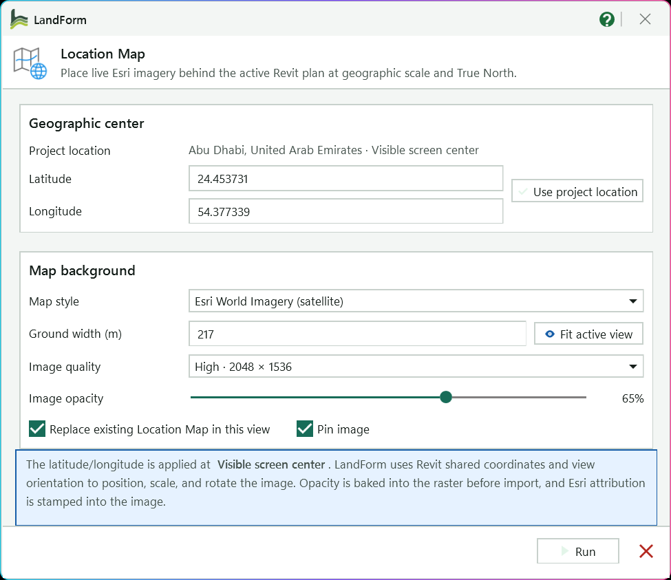
Place name and where the map is centred, normally the Visible screen center.
Coordinates of the map centre; type other values to map a different spot.
Restores the latitude and longitude worked out for the view.
Esri World Imagery (satellite) or Esri World Topographic.
Real-world width of the image, 25 m to 20,000 m; the height follows the image proportions.
Returns to the width that covers the visible area.
Standard, High or Very high.
Fades the image against white so linework stays readable on top.
Swap out a map placed earlier, and pin the new image so it cannot be moved by accident.
Explains where the centre is applied and how the image is positioned, faded and credited.
Downloads the map, places it behind the plan and selects the new image.
Open LandForm tab → Annotation panel → Location Map.
Frame the view. Zoom the active plan to the area the map should cover, then start Location Map.
Check the centre. Under Geographic center, Project location shows the place name and where the map will be centred, normally the Visible screen center. Latitude and Longitude are filled in for that point; type other values to map a different spot, or press Use project location to restore them.
Choose the map. Pick a Map style: Esri World Imagery (satellite) or Esri World Topographic.
Set the coverage. Ground width (m) is the real-world width of the image, between 25 m and 20,000 m; its height follows the image proportions. Press Fit active view to go back to the width that covers the visible area.
Set quality and opacity. Choose an Image quality (Standard, High or Very high) and drag Image opacity to fade the image against white, so linework stays readable on top.
Choose the options. Leave Replace existing Location Map in this view on to swap out a map placed earlier, and Pin image on so it cannot be moved by accident.
Run. Press Run. LandForm downloads the map, places it and selects the new image. A summary reports the centre, the coverage in metres, the opacity and any map it replaced.
The plan now has one raster image on the background layer, behind all model graphics, scaled to the ground width you set and rotated so that it matches True North in this view, rotated views included. The pixels are embedded in the project as an image type named "LandForm Location Map - Satellite" or "- Topographic" followed by the date, so there is no external file to keep track of. The placement is one step in Revit's Undo list, "LF-Location Map: Place Background".
No separate LandForm window. This command runs directly from Revit selection and prompts; follow the workflow above and the messages shown beside the cursor or on Revit's status bar.
LandForm ribbon panel
Quality checks and studios for sun, sight lines, slopes, bubble diagrams and play areas.

Analysis · QA/QC · Plant Distance
Plant Distance is the QA/QC pass to run before a planting plan goes out: a tree set too close to a footpath means lifted paving later, and a shrub placed on the path blocks it. You pick the Floors that represent the paths and type the clearance; the view turns into a review, with the paths outlined in blue, every failing plant filled red with a witness line to the nearest path edge, and the rest of the model greyed out. A report lists each failing plant with its actual distance. Resolve previews a fix in green and Apply moves the planting so it sits exactly at the minimum clearance.
LandForm tab→Analysis panel→QA/QC ▾→Plant Distance
Button tooltip: “Check tree and plant clearance from a path.”Plant Distance walkthrough. Until it is published, the steps and the annotated window below walk through the same workflow.
Numbers on the screenshot match the legend. Hover a number or a legend row to highlight the other.

Minimum clearance between planting and the path edge, in metres; it must be greater than zero.
Click one or more path Floors in Revit and press Finish; the review runs as soon as the pick ends.
Names the selected paths and the minimum distance.
Runs the check again with the current paths and minimum, and clears any preview.
Previews the proposed moves in green without changing the model; enabled only when plants fail.
Moves the planting as previewed in one undoable step; enabled only while a preview is showing.
Open LandForm tab → Analysis panel → QA/QC ▾ → Plant Distance.
Open the report bar. The compact Plant Distance Report window appears at the top of the drawing area with Select Path, the Min. box, Refresh, Resolve, Apply and a close button. Nothing in the view changes yet.
Set the clearance. Type the minimum distance in metres into Min.. It must be a number greater than zero; anything else is refused with a warning.
Pick the paths. Press Select Path, click one or more path Floors in Revit and press Finish. The review runs at once: the paths turn blue, everything else goes halftone grey, and every plant closer than the minimum is filled solid red with a red line to the nearest path edge.
The distance is measured in plan, from the plant's placement point to the nearest edge of the floor's top face. A plant standing on a path is measured to the edge of that path.
Read the report. The window grows to show CHECKED, COMPLIANT and FAILED counts and the Non-compliant planting list, closest first, with each plant's type name, element ID and actual distance in metres. The status line names the selected paths and the minimum.
Refresh after changes. Change Min. or move planting in Revit, then press Refresh to run the same paths again. Press Select Path to pick a different set of paths.
Preview the fix (optional). Press Resolve. Each failing plant is drawn in green at its proposed position with a green line from where it stands now. The move is perpendicular to the nearest path edge and just long enough to reach the minimum clearance; a plant standing on the path is moved off it.
Apply. Press Apply to move the planting in one undoable step named "LF-Plant Distance: Resolve Non-Compliance". The check runs again and the moved plants stay highlighted green so you can see what changed. Plants that are pinned, grouped or owned by another user stay where they are, and a warning says so if none could be moved.
Close. Press the close button or Close & Clear. The red, blue and grey overrides are removed and the view looks as it did before.
While the window is open, the active view carries temporary graphic overrides: blue path outlines, red failing planting, grey context and the red or green witness lines. Closing the window restores every override, so nothing about the view is left behind. The model itself changes only when you press Apply: each moved plant is shifted in plan to exactly the minimum clearance from the path edge, keeping its type, level and host; the move is one entry in Revit's undo list, and the green highlight marks the moved plants until you close or refresh.
Returns to Revit so you can pick one or more path Floors and press Finish; the review runs as soon as the pick ends.
Minimum permitted clearance between planting and the path edge, in metres. Must be greater than zero.
Runs the check again with the current paths and minimum distance, and clears any resolution preview.
Previews the proposed perpendicular moves in green without changing the model. Enabled only when there are failures.
Moves the planting as previewed in one undoable step and highlights the moved plants green. Enabled only while a preview is showing.
Closes the window, clears the preview and restores the view's graphics.
The same as Close, from the report footer.

Analysis · QA/QC · Untagged Elements
Untagged Elements is the check to run on a planting plan, a site plan or a detail before it goes on a sheet. It collects the taggable model elements the view shows (planting, site furniture, walls, floors, families of any model category), reads every tag placed in the same view and compares the two. A short report tells you how many elements are untagged out of how many were checked, and the untagged ones are highlighted and selected in the view.
LandForm tab→Analysis panel→QA/QC ▾→Untagged Elements
Button tooltip: “Highlight visible model elements without a tag.”Untagged Elements walkthrough. Until it is published, the steps and the annotated window below walk through the same workflow.
Numbers on the screenshot match the legend. Hover a number or a legend row to highlight the other.
Names the check that wrote the report.
How many elements no tag in this view points at; it reads "No untagged model elements found" when every candidate has a tag.
How many taggable model elements the view shows.
Each run clears the previous red before it highlights again.
Closes the report; the untagged elements stay selected and red in the view, ready for tagging.
Open LandForm tab → Analysis panel → QA/QC ▾ → Untagged Elements.
Run the check. There is nothing to set: the tool reads the active view as soon as you start it.
Read the report. A dialog reports either "Highlighted N untagged element(s) in red" with how many visible candidates were checked, or "No untagged model elements found" when every candidate has a tag.
Review the view. Each untagged element is drawn with heavy red lines and a solid red fill, and all of them are left selected. Tag them with Revit's tag tools, or zoom to the selection to find the stragglers.
Tag and run again. Every run first restores the graphics it changed on the previous run, then applies the new highlight, so the red never accumulates. Run the tool once more when everything is tagged and the view returns to normal.
No model element is changed. The red is a per-element graphic override in the active view, applied in one step named "LF-Untagged Elements: Highlight Untagged Elements" and removed by the next run ("LF-Untagged Elements: Clear Highlight") or by Undo. The untagged elements remain selected after the dialog closes, ready for tagging.
No separate LandForm window. This command runs directly from Revit selection and prompts; follow the workflow above and the messages shown beside the cursor or on Revit's status bar.

Analysis · Studios · Sun Analysis
Sun Analysis (the Sun Studio workspace, under Analysis > Studios) opens the visible model, links included, in a 3D viewer that places the sun from the project's site location, true north and time zone. Scrub the day and the shadows follow; pick the surfaces that matter and read their shaded share at any time of day; run a period and a heatmap builds over every surface in view. You can also sketch paths, areas and planting that exist only in the studio, to test a design idea before it is modelled. The model is only changed when you Bake to Revit or Commit to Revit.
LandForm tab→Analysis panel→Studios ▾→Sun Analysis
Button tooltip: “Render the active view with real-time shadows and a sun-hours heatmap.”Sun Analysis walkthrough. Until it is published, the steps and the annotated window below walk through the same workflow.
Numbers on the screenshot match the legend. Hover a number or a legend row to highlight the other.
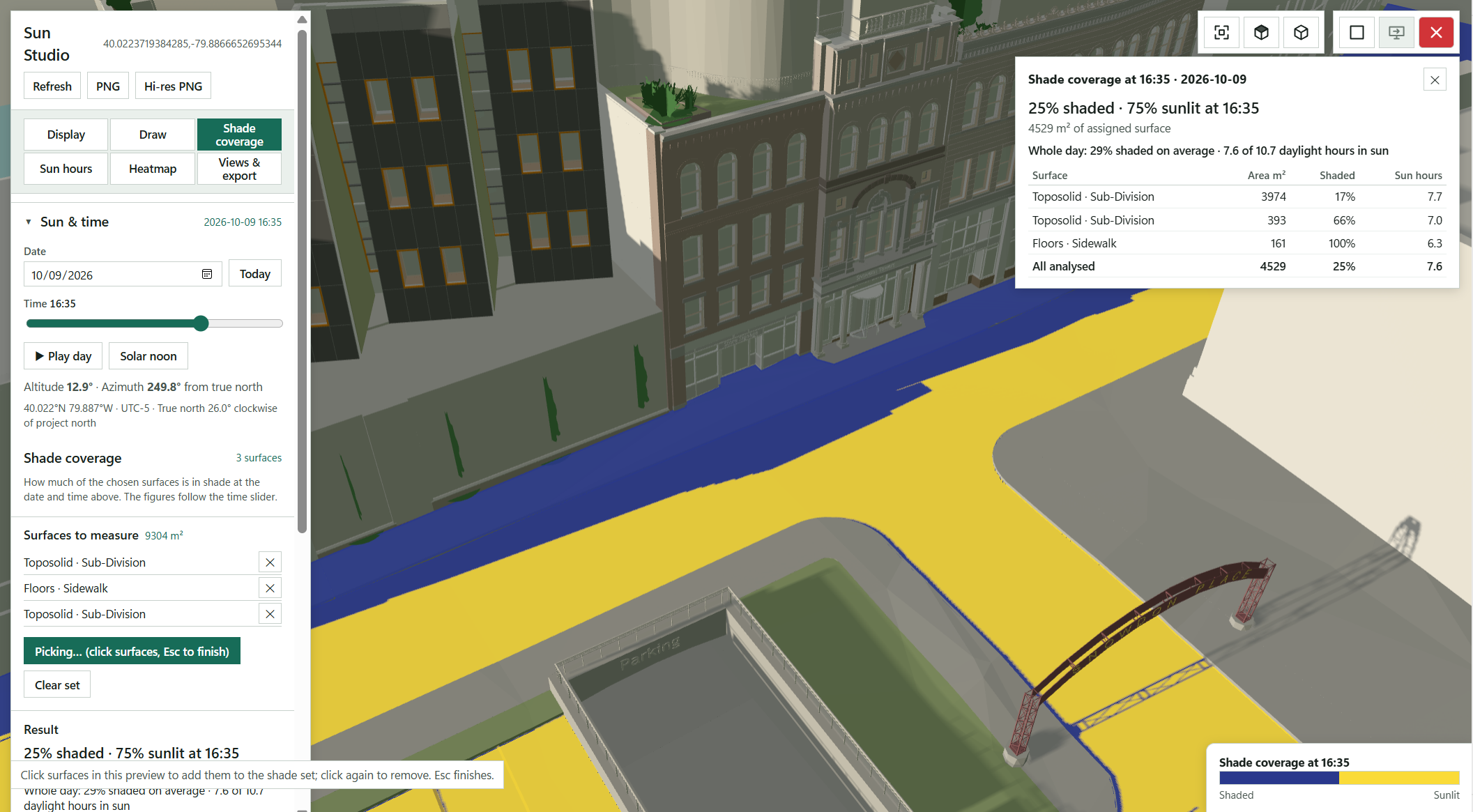
Refresh re-reads the model after edits; PNG and Hi-res PNG save a picture of the preview.
Fit the model in the preview, or switch to a top or 3D view.
Display, Draw, Shade coverage, Sun hours, Heatmap and Views & export switch the panel; here Shade coverage is open.
The visible model with real-time shadows, the picked surfaces painted blue where shaded and yellow where sunlit. Middle-drag orbits, Shift + middle-drag pans, the wheel zooms.
Pick the Date (Today is one click) and drag the Time slider; the shadows follow.
Sweeps through the day, or jumps to solar noon.
The sun's position, with the site's location and true north below.
The Pick surfaces button while a pick runs: click the terraces, lawns and play areas in the preview.
Click a surface to add it to the shade set, click again to remove it; Esc finishes.
The picked surfaces and their total area.
Shaded share at the slider time, followed by the whole-day average.
The table from Show the table: area, shaded share and sun hours per surface and for all analysed.
The Shaded and Sunlit colours painted on the counted surfaces.
Open LandForm tab → Analysis panel → Studios ▾ → Sun Analysis.
Open the viewer. The studio reads the active view, shows its progress and fits itself over the Revit window. The toolbar gives Zoom extents, Top, 3D, Refresh, PNG and Hi-res PNG; middle-drag orbits, Shift + middle-drag pans, the wheel zooms at the cursor and right-click opens the view menu. The tabs Display, Draw, Shade coverage, Sun hours, Heatmap and Views & export switch the panel; Sun & time stays above them.
Set the sun. Under Sun & time, pick the Date (Today is one click) and drag the Time slider; the shadows follow. Press Play day to sweep the day, Solar noon to jump to it. The readout gives the sun's altitude and azimuth and the site line shows the location and true north.
The studio starts at the date and time of the view's own sun settings.
Choose how the model looks (Display). Pick a View style: Category colours, Revit material colours, Realistic (materials, glass, sky), Black & white, Black & white, planting green, White with edges or White with edges, planting green. Planting renders as modelled or as lollipop trees for flat (RPC) plants or for all planting. Switch on Edges, Sun path diagram, Orthographic view, Ground plane and Soft shadows as you need.
Under Categories, untick a category to leave it out entirely (not drawn, no shadow, not analysed), give it a colour with its swatch, or slide it see-through: a transparent category still casts its shadow and is still analysed, which Revit's own transparency does not do.
Measure shade coverage. On the Shade coverage tab press Pick surfaces and click the terraces, lawns and play areas in the preview; they are listed under Surfaces to measure with their area. The Result block gives the shaded share at the time on the slider, follows the slider as you move it, and adds a whole-period average for the Period for the average you choose. Show the table floats a per-surface table (surface, area, shaded, sun hours) over the preview.
Under Options, set the Sample grid (m), tick Include vertical faces to count walls (top faces only by default; undersides never), and choose whether the counted surfaces are painted in the Shaded and Sunlit colours.
Run sun hours, radiation or sky view. On the Sun hours tab pick the Metric: Direct sun hours, Incident radiation (kWh/m², needs EPW) or Sky view factor. Choose the Surfaces (Picked surfaces (shade set), Terrain & paving, Clicked element or All surfaces), the Grid (m) and press Run. The result colours the surfaces with a legend and fills the per-surface table.
The period, daily window and sample interval for this run are the ones set on the Heatmap tab.
Build a heatmap of the view (Heatmap). Set Analysis to Sun-hours heatmap or Shade-hours heatmap, choose the Period (This date, 21 June, 21 December, 21 March (equinox), Solstices + equinox, This month, Three months from this date or Whole year), the From and To hours and Sample every 60, 30, 20 or 10 minutes. The heatmap builds progressively over everything in view, pauses while you navigate and restarts when the camera moves. Tick Highlight ≥ to mark the places that reach a number of hours, and set its opacity.
Sketch design ideas (Draw, optional). Choose Path, Area or Plant and click in the preview; Enter, a double-click or clicking the first corner finishes, Backspace takes a point back and Esc cancels. A path has a Width (m), a Style (Straight or Curved), a Surface (Paving, Lawn, Planting bed or Water) and a Colour; a plant takes a Plant family type from the model's planting families (searchable), a Shape in the studio, a Mature size and an Installation size. Sketched items cast and receive shadows and are counted in Shade coverage when ticked in the Sketched items list; click an item's name for grips to reshape it, ✎ to rename it.
Convert model trees… turns the model's planting into studio trees with a mature size and an installation size per type, and Show and analyse studio trees at switches between the two. Commit to Revit… creates the sketched paths, areas and plants as Revit elements of the types you choose, on a Level, draped with shape points when Follow the surface below is ticked.
Save, report and bake (Views & export). Save view keeps a snapshot of everything (date and time, display, analysis settings, picked surfaces, camera), named by date and time and renamed with ✎. Save study… writes the whole setup to a .lfsun file and Load study… brings it back. Report PDF and CSV export the current analysis; Batch export… renders a matrix of dates and times (this date, 21 March, June, September and December, the 21st of every month, or a custom list; times as a range or a list) as one PDF page per frame with the shade table, optionally with a PNG per frame. Bake to Revit writes the analysis into the active Revit view as an Analysis Visualization with a legend.
Nothing in the model changes until you ask for it. Bake to Revit writes the shaded/sunlit, sun-hours, radiation or sky-view values onto the faces of the analysed elements in the active 3D, plan or section view as an Analysis Visualization, with a blue-to-red legend in a display style named "LandForm Sun Studio"; one bake per view, so a new bake replaces the earlier one, and points on linked elements are reported and skipped. The undo entry is named "LF-Sun Studio: Bake …" after the metric. Commit to Revit… creates the sketched paths and areas as floors or toposolids and the sketched plants as family instances, each with "LandForm Sun Studio sketch - name" in Comments, in one step named "LF-Sun Studio: Commit Sketch"; the committed items leave the sketch and the view is read again so they come back as real elements. PDF, CSV, PNG and .lfsun studies are files you choose a location for.
No separate LandForm window. This command runs directly from Revit selection and prompts; follow the workflow above and the messages shown beside the cursor or on Revit's status bar.

Analysis · Studios · Isovist Analysis
Isovist Analysis (the Isovist Studio workspace, under Analysis > Studios) opens everything the active view shows, including linked models, conceptual masses and the project's CAD files, in a workspace over the Revit view. An isovist is the area a viewer can see from one spot. Use it for sightlines and view corridors, natural surveillance and safety reviews, how open or enclosed a space feels, and where a landmark or a sign can be seen from. The model is only changed when you create filled regions or bake an analysis display.
LandForm tab→Analysis panel→Studios ▾→Isovist Analysis
Button tooltip: “Map what can be seen from where: plan isovists, visibility fields and 3D viewsheds.”Isovist Analysis walkthrough. Until it is published, the steps and the annotated window below walk through the same workflow.
Numbers on the screenshot match the legend. Hover a number or a legend row to highlight the other.
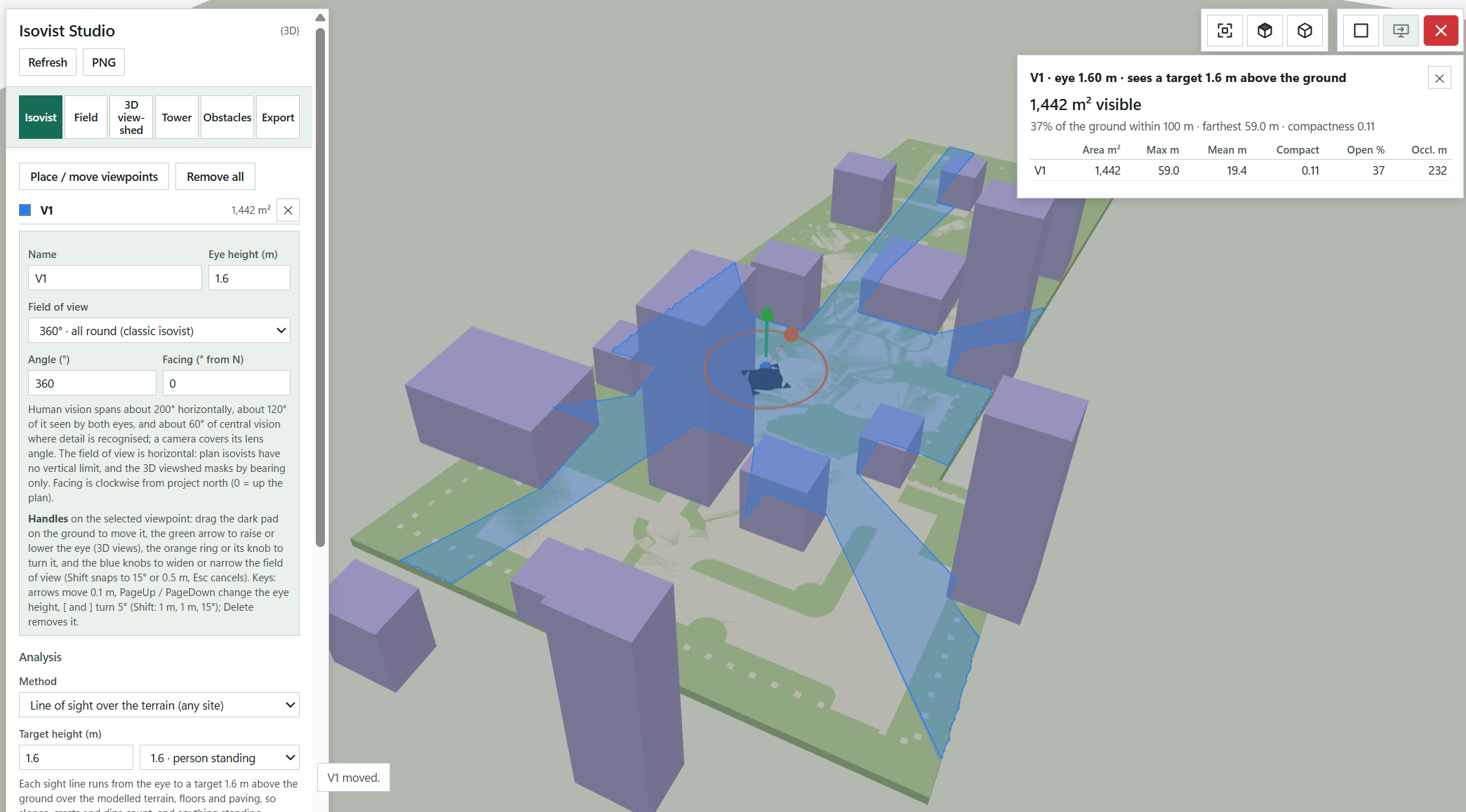
Re-reads the visible model, or saves the preview as an image.
Fits the model in the preview and switches between plan and 3D.
Isovist, Field, 3D viewshed, Tower, Obstacles and Export hold each part of the study.
Click where a viewer stands, on the terrain, a floor or a terrace (shortcut P).
Names the selected viewpoint and sets its eye height.
Picks a field-of-view preset or a custom angle, and the facing clockwise from project north.
Drag the dark pad to move the viewpoint, the green arrow to raise the eye and the orange ring to turn it.
Line of sight over the terrain follows the ground; the eye-level plan cut suits flat sites.
How far above the ground each sight line aims: 1.6 m for a standing person, 0 for the ground itself.
Visible area, share of the ground within the view distance, farthest sightline, openness, compactness and occlusivity for the viewpoint.
Confirms the last action, here a moved viewpoint.
Open LandForm tab → Analysis panel → Studios ▾ → Isovist Analysis.
Open the workspace. The visible model is read and the studio fits over the Revit view. The toolbar gives Zoom extents, Plan, 3D, Refresh and PNG; the tabs are Isovist, Field, 3D viewshed, Tower, Obstacles and Export.
Place the viewpoints. Press Place / move viewpoints (P) and click where a viewer stands: on the terrain, a floor or a terrace. Each viewpoint gets a Name, an Eye height (m), a Field of view (360° · all round (classic isovist), 200° · whole human field, 120° · both eyes (binocular), 60° · central vision, camera or a custom Angle) and a Facing in degrees clockwise from project north.
The selected viewpoint shows handles: drag the dark pad on the ground to move it (it follows the surface under the pointer), the green arrow to raise or lower the eye in a 3D view, the orange ring or its knob to turn it, and the blue knobs on the wedge edges to widen or narrow a limited field of view. Shift snaps to 0.5 m and 15°, Esc cancels a drag. Arrow keys move the viewpoint 0.1 m, PageUp and PageDown change the eye height by 0.1 m, [ and ] turn it 5° (with Shift: 1 m, 1 m, 15°) and Delete removes it.
Choose the method. Line of sight over the terrain (any site) follows the ground: each sight line runs from the eye to a Target height (m) above the ground, 1.6 m to see a standing person, 1.0 m for a child or a seated person, 0 to see the ground itself. Slopes, crests and dips count, and anything standing in between blocks the line only where it is tall enough, so a sight line passes under a tree canopy or over a low wall. Eye-level plan cut (flat sites, classic) cuts the obstacles at each viewer's eye level; it is exact on flat ground, where both methods agree when the target is at eye height.
Set the View distance (m), the number of Rays (360 to 2880) and the Default eye height (m) for new viewpoints. Under Display, switch the Isovist fill, Sight rays, the Obstacle cut at eye level and Draw isovists on top of the model, and set the Fill opacity.
Read the measures. The card for the selected viewpoint gives the visible area, the share of the ground within the view distance, the farthest sightline, openness (rays that reach the view distance), compactness (how enclosed the space is) and occlusivity (the length of hidden edges). With two or more viewpoints it also gives the area seen by at least one and by two or more, and which landmarks each sees.
Run a field (Field tab). Choose the Surfaces (Terrain, floors & paving, or Picked surfaces you click with Pick surfaces), the Grid (m) and the Measure: Visible area, Longest sightline, Mean sightline, Compactness, Openness, Occlusivity, Seen by viewpoints or Sees landmarks. Press Run: an isovist runs from every grid point and the grid is coloured by the measure, with a legend. CSV exports the points and Bake to Revit writes the field onto the surfaces in the active Revit view as an Analysis Visualization.
Show the 3D viewshed. On the 3D viewshed tab tick Show 3D viewshed to see, from any camera, what the viewpoints actually see on the terrain, facades and roofs. Choose From all viewpoints or the selected one, and the Colouring: Visible / hidden in the two colours you set, or the Number of viewpoints that see it.
Study tall buildings (Tower tab). Press Place landmarks (L) and click points that matter to the view: the sea, a park, a monument, the top of a tower; the height lifts the target above the clicked point. For floor-by-floor views press Pick building (B) and click a building or a mass (touching elements of the same model come with it; click again to add or remove). Choose the Floors (Automatic, Mass floors only, Revit levels only or Every floor height), the Floor height (m), Façade spacing (m), View distance (m), Eye above floor (m) and Rays per point, then press Run. The façade is coloured by the chosen measure (Open view (%), Longest view (m), Ground seen (m²) or Landmarks seen) and the table lists every floor, top floor first, with heights measured from the building's base.
To map the visual impact of a tower, place a landmark on its top and run the Field with Sees landmarks.
Decide what blocks the view (Obstacles tab). Switch the model categories (Buildings, walls & other model elements, Massing (conceptual masses), Planting, and for the eye-level cut also Terrain (toposolids), Floors & paving and Water), each Revit link, each CAD file and its layers. Under CAD lines stand, choose whether CAD lines block at Full height, or stand 1 m (hedge, low wall), 2 m (fence, screen) or 3 m (wall) above the modelled ground.
Export and create in Revit (Export tab). Report PDF, Viewpoints CSV and Hi-res PNG export the study. Isovists as filled regions draws each viewpoint's visible area in the active plan view. Save study… keeps viewpoints, settings, obstacle choices and camera in a .lfiso file; Load study… brings them back.
The model is unchanged until you bake. Isovists as filled regions creates, in the active plan view, one filled region per visible patch (with its holes) of a type named "LandForm Isovist", coloured like its viewpoint at 50 % transparency, with the viewpoint's name, visible area, eye height and method written to Comments, a small circle and a label (name and area) at the viewer, all grouped as a detail group "Isovist name"; the step is named "LF-Isovist Studio: Bake Isovists" and the groups are selected afterwards. Bake to Revit on the Field and Tower tabs writes the values onto the analysed faces of elements of this model as an Analysis Visualization with a legend ("LandForm Isovist Studio" display style); one bake per view, so a new bake replaces the earlier one, and points on linked elements are reported and skipped.
No separate LandForm window. This command runs directly from Revit selection and prompts; follow the workflow above and the messages shown beside the cursor or on Revit's status bar.

Analysis · Studios · Bubble Diagram
Bubble Diagram (the Bubble Studio workspace, under Analysis > Studios) is the early-concept tool: drop the spaces a site needs and let them find their place. Each preset carries its own rules, so a patio pulls toward the building and the entrance, a play area keeps clear of roads and parking, planting beds hug the boundary, and everything packs inside the site and away from the trees. A score tells you how well each space sits, and the whole diagram can be shuffled, kept as an option and finally drawn in Revit.
LandForm tab→Analysis panel→Studios ▾→Bubble Diagram
Button tooltip: “Sketch a bubble diagram of the site program that reacts to the site by rules.”Bubble Diagram walkthrough. Until it is published, the steps and the annotated window below walk through the same workflow.
Numbers on the screenshot match the legend. Hover a number or a legend row to highlight the other.
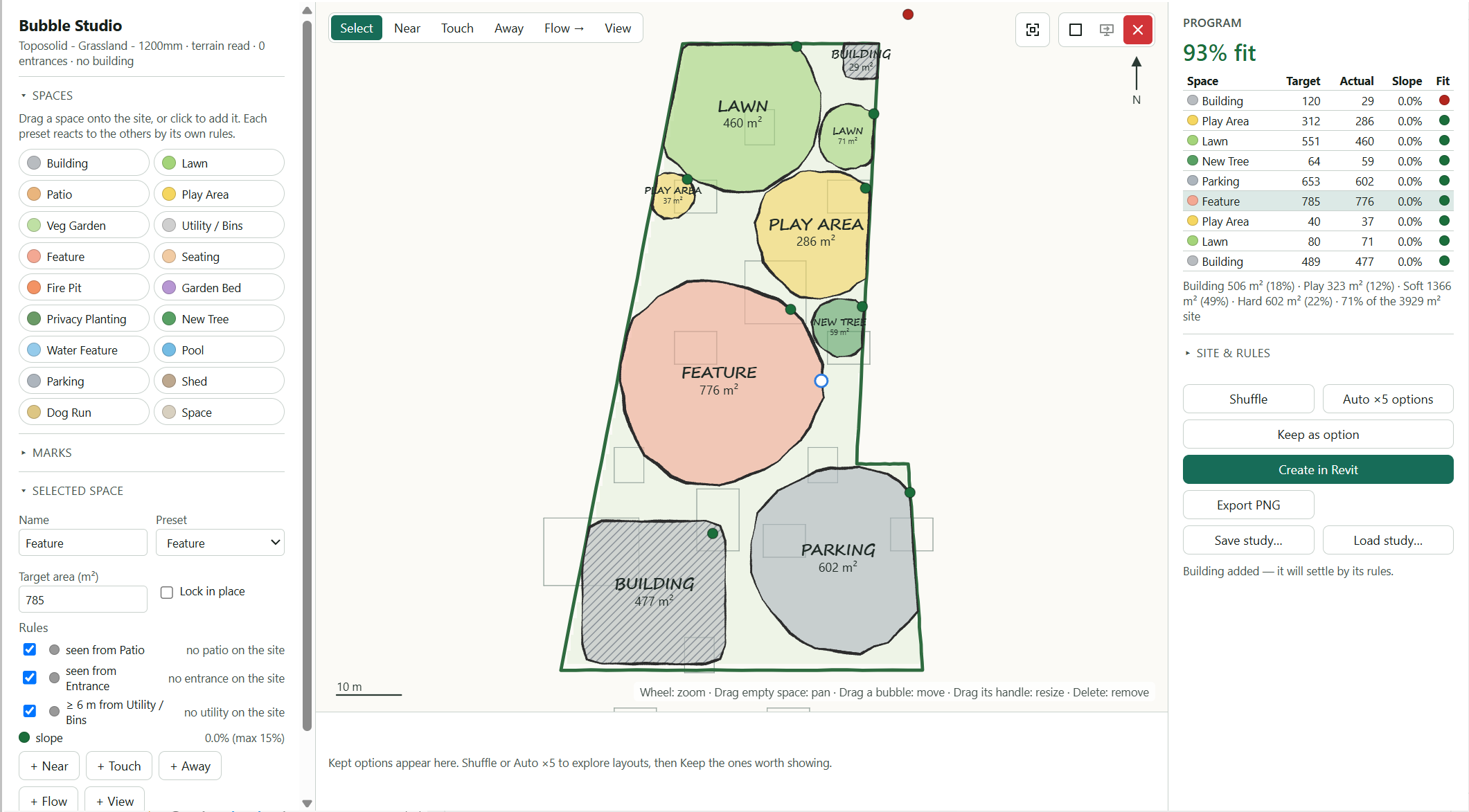
Names the site you picked and what was read around it: terrain, entrances and building.
Drag a space onto the site, or click it to add it; each preset reacts to the others by its own rules.
The bubbles settle inside the site boundary. Drag a bubble to move it, drag its handle to resize it, press Delete to remove it.
Reports what just happened, such as a space added and settling by its rules.
Name, Preset, Target area (m²), Lock in place and the rules the clicked bubble follows.
Adds a relationship from the selected space; click the other bubble or a site anchor next.
Draws the same relationships directly on the plan between two bubbles; Select returns to moving.
Expands the marks palette: symbols and line marks to annotate the diagram; only Entrance counts for the rules.
Overall fit score, then every space with its Target, Actual area, Slope and Fit, and totals by kind below.
Expands Live rules, the display switches, Gap between bubbles (m), Reaction strength, Settle now and Clear all spaces.
Finds a new arrangement, generates five layouts, or stores the current one as an option.
Kept options appear here, so you can bring one back and compare.
Draws the diagram on the active plan view as coloured filled regions, labels and link lines.
Captures the sketch as an image, or keeps the diagram between sessions.
Open LandForm tab → Analysis panel → Studios ▾ → Bubble Diagram.
Pick the site. At the prompt "Select the site: a property line, floor or toposolid", click the element. The studio window opens over the Revit view with the site boundary, the terrain tinted by slope and the surrounding buildings, roads, paving and trees drawn as context.
Drop the spaces. Drag a space from the Spaces palette onto the site, or click it to add it: Building, Lawn, Patio, Play Area, Veg Garden, Utility / Bins, Feature, Seating, Fire Pit, Garden Bed, Privacy Planting, New Tree, Water Feature, Pool, Parking, Shed, Dog Run or a plain Space with no rules. Each bubble attracts, repels and packs by its preset's rules and settles into place; a fit score shows how well it sits.
Drag a bubble to move it, drag its handle to resize it, press Delete to remove it. Use Building on a site whose building is not in the model: it becomes the anchor every "building" rule looks for.
Tune a space. Click a bubble: the Selected space panel shows its Name, Preset, Target area (m²), Lock in place and the list of rules it follows. Duplicate and Delete act on it.
Add relationships. With a space selected, press + Near, + Touch, + Away, + Flow or + View and click the other bubble, or a site anchor such as the entrance or the building. The toolbar modes Near, Touch, Away, Flow → and View do the same directly on the plan between two bubbles; Select returns to moving.
Add marks. Drag or click Marks for things the diagram should respond to or annotate: Focal point, Heart, Star, Sun, Shade, Existing tree, Water / wet, Noise, Avoid, Entrance, Node, Question, Tick, and the line marks Arrow, Two-way, Circulation, View cone, Wind, Screen, Barrier and Zone edge. A selected mark takes a Label, a Size (m) and a Colour; Flip swaps the ends of a line mark. Marks carry no rules, except that an Entrance mark counts as an entrance for the spaces that look for one.
Read the programme and set the behaviour. The Program table lists every space with its Target, Actual area, Slope and Fit, with the overall score above and totals by kind below. Under Site & rules, switch Live rules (bubbles keep reacting as you work), the slope tint, the surrounding elements and the rule lines of the selected space, set the Gap between bubbles (m) and the Reaction strength, press Settle now to relax the current arrangement once, or Clear all spaces to start over.
Explore options. Shuffle finds a new arrangement, Auto ×5 options generates five layouts, and Keep as option stores the current one on the options strip under the plan, where you can bring it back and compare.
Create in Revit. With a plan view active, press Create in Revit. Export PNG captures the sketch, Fit view recentres it, and Save study… and Load study… keep the diagram between sessions.
The active plan view gets a detail group named "Bubble Diagram" (plus the option's name when it has one) containing one solid filled region per space, of a type named "LandForm Bubble" and coloured in the space's colour, with the preset, kind, target and actual area, slope and fit written to Comments; a centred text note with the space's name and area; detail lines for the links, with arrowheads on flows; and the marks as detail lines with their labels. The whole creation is one undoable step named "LF-Bubble Studio: Bake Diagram", and the group is selected afterwards. The diagram stays in the studio so you can keep working on it.
No separate LandForm window. This command runs directly from Revit selection and prompts; follow the workflow above and the messages shown beside the cursor or on Revit's status bar.

Analysis · Studios · Playground
Playground is the studio for play areas. You drag generic equipment onto the site and every impact area and free space follows it, sized from the free height of fall; clashes show at once, the impact surfacing is worked out for you, and a scorecard tracks the kinds of play, age groups, capacity and shade. Snapping, design presets, EPDM surface graphics and kept options help you compare arrangements before anything is modelled. When one is right, Create in Revit builds it with the play data written to every element.
LandForm tab→Analysis panel→Studios ▾→Playground
Button tooltip: “Lay out a playground with live EN 1176 safety zones, surfacing, age groups and play value.”Playground walkthrough. Until it is published, the steps and the annotated window below walk through the same workflow.
Numbers on the screenshot match the legend. Hover a number or a legend row to highlight the other.
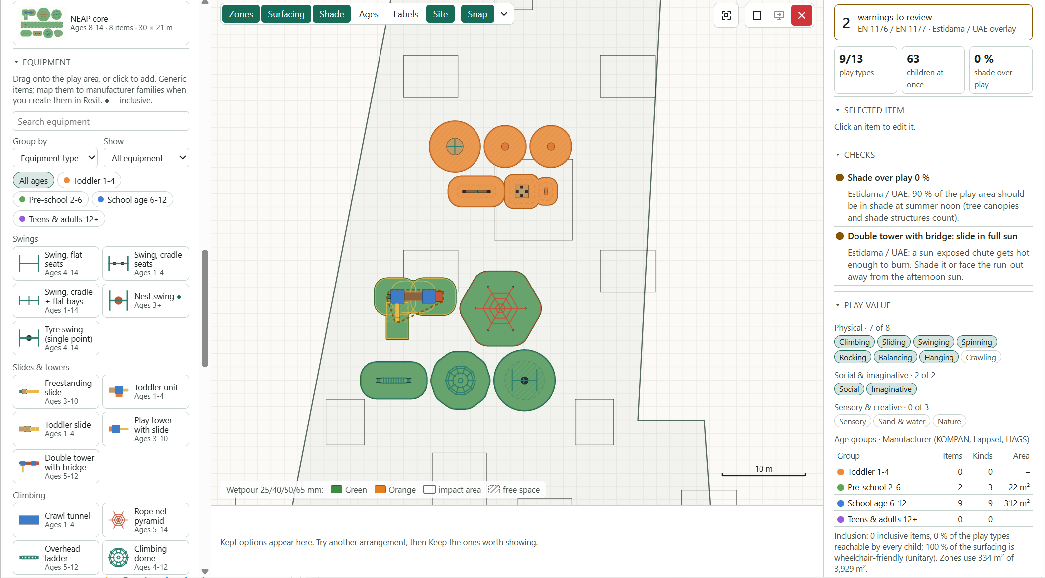
Filter the catalogue by name, group it, show inclusive items only or pick an age chip.
Drag an item onto the play area or click it to add it; hover for a 3D preview with its size and ages.
Each item carries its impact area and free space, which follow it as you move or rotate it.
Turns snapping on or off (F3); the chevron opens the snap settings.
The verdict box counts issues and warnings against the chosen standard and overlay.
Lists each finding with the reason; click one to focus it on the plan.
Switch those layers on the plan on or off.
Legend for the surfacing colours, impact areas and free spaces.
Click an item to set its rotation, surfacing, age group, colour and parameters here.
A design preset; hover it for its principles and contents, then drag it onto the plan.
The scorecard tiles for the current layout.
The kinds of play covered, broken down by age group, with the inclusion summary.
Arrangements stored with Keep as option appear here as cards; click one to restore it.
Open LandForm tab → Analysis panel → Studios ▾ → Playground.
Pick the play area. If a suitable element is already selected it is used; otherwise click the floor, toposolid, filled region or property line. The Playground window opens over the Revit view with the play area outlined and the buildings, walls, paving and trees around it drawn as context.
Set the standard, surfacing and ages. Under Standard choose the Safety standard, tick Estidama / UAE overlay (shade, hot surfaces) if it applies, and set the Default impact surfacing, the Wetpour colour (EPDM) and Graphics elsewhere (mm), the thickness of EPDM graphics laid outside the impact surfacing. Under Ages pick the Age groups scheme: manufacturer catalogue steps, the US groups, the UK Fields in Trust areas (LAP, LEAP, NEAP) or an under-3 split.
Add equipment. Under Equipment, search, Group by equipment type, age group or kind of play, show Inclusive only, or filter by age chips. Drag an item onto the play area or click it to add it. Hover an item for a 3D preview with its size, ages, free height of fall and links to matching product ranges. The catalogue covers swings, slides and towers, climbing, balance and nature play, spinning and rocking, sand, water and sensory play, shade sails and benches; inclusive items carry a dot.
Place precisely. Equipment snaps to endpoints and corners, midpoints, centres of other equipment, graphics and trees, the nearest edge, or a grid; while moving, alignment guides appear, safety zones slide to just touch a neighbour's or the boundary, and rotation snaps parallel to nearby edges. The Snap button (or F3) turns snapping off, the chevron beside it opens the snap settings, and holding Alt places freely. Drag an item's handle or press R to rotate it; the arrow keys nudge it.
Watch the checks. The verdict box at the top right counts issues and warnings, and Checks lists them: overlapping free spaces, equipment inside another item's zone, trees, walls and buildings in a zone, zones running past the boundary, equipment too close to a fence or tree, toddler play beside older children's equipment, and sun on slides under the Estidama overlay. Click a finding to focus it. The Zones, Surfacing, Shade, Ages, Labels and Site buttons switch the layers on the plan.
Edit the selected item. The Selected item panel shows a 3D preview and lets you set Rotation (°), the item's own Surfacing, its Age group, its Surface colour and its parameters (seat count, platform height and so on). Rotate 90°, Duplicate and Delete act on the selection.
Add surface graphics. Under Surface graphics, pick an EPDM colour, then drag a shape, letter, number or game (hopscotch, number track, alphabet trail, stepping spots, compass) onto the plan. Edit its Text, Font, Rotation and colours, and use Bring forward and Send back to set the drawing order. A free shape is drawn corner by corner; Enter or a double-click closes it.
Try a design preset. Under Design presets, hover a preset for its design principles and contents, then drag it onto the plan. Place as decides whether it arrives as One group (moves and turns together) or Separate items. Click a group member to move, rotate or duplicate the whole group; double-click a member to edit it alone; the group panel offers Ungroup when you want the pieces apart.
Read the scorecard. The tiles count play types covered (out of 13), children at once and shade over play. Play value breaks the kinds of play down by age group, and Surfacing lists the area and thickness of every material and colour.
Keep options and create. Press Keep as option to store the current arrangement as a card under the plan (Option A, B and so on); click a card to restore it. Under Create in Revit, tick Equipment as LandForm families, Impact surfacing as floors and Impact areas and free spaces on the plan view, then press Create in Revit. If the checks still list issues, a dialog asks whether to create anyway.
Export PNG saves the plan, and Save study… writes the layout and kept options to an .lfplay file that Load study… reopens later.
The chosen layout now exists in the model in one undo step named "LF-Playground: Create Play Layout". Each piece of equipment is a Site-category family generated from its generic geometry, named LF-PLAY plus the item and its size, placed on the ground and selected when the tool finishes. Impact surfacing is a set of flat floors whose types are named after the material, thickness and colour, with EPDM graphics as separate floors in their own colours. Impact areas and free spaces are filled regions of the types LF-PLAY Impact Area and LF-PLAY Free Space, coloured per item and grouped as LF-PLAY Safety Zones. Equipment and floors carry the play data as shared parameters (LF_Play Item, LF_Play Free Height of Fall, LF_Play Users, LF_Play Ages, LF_Play Types, LF_Play Inclusive, LF_Play Surfacing, LF_Play Standard, LF_Play Option, LF_Play Age Group and LF_Play Product Link), ready for schedules. The status line reports what was created.
| Key | Action |
|---|---|
| R / Shift+R | Rotate the selection 15° clockwise / anticlockwise |
| Arrow keys | Nudge the selection 0.1 m (1 m with Shift) |
| Ctrl+D | Duplicate the selection |
| Delete or Backspace | Delete the selection |
| Ctrl+Z / Ctrl+Y | Undo / redo |
| F3 | Snapping on or off; hold Alt to move freely |
| Enter / Esc | Close / cancel a free shape; Esc also clears the selection |
| Home | Fit the plan in the window |
No separate LandForm window. This command runs directly from Revit selection and prompts; follow the workflow above and the messages shown beside the cursor or on Revit's status bar.

Analysis · Studios · Sketchy
Sketchy (the Render Studio workspace) is for the moment a client wants to see the idea, not the model. It reads what the view shows, links included, and redraws it in a marker, watercolour, ink or pencil style with wobbly linework and a library of planting symbols. You can switch categories and single elements off, recolour them, draw over the top with pen, marker, text and stamp tools, and add diagram marks and redline markups. Nothing in the model changes until you choose Place in view, and even then the only new element is an image.
LandForm tab→Analysis panel→Studios ▾→Sketchy
Button tooltip: “Redraw the active view as a hand sketch with a planting symbol library.”Sketchy walkthrough. Until it is published, the steps and the annotated window below walk through the same workflow.
Numbers on the screenshot match the legend. Hover a number or a legend row to highlight the other.
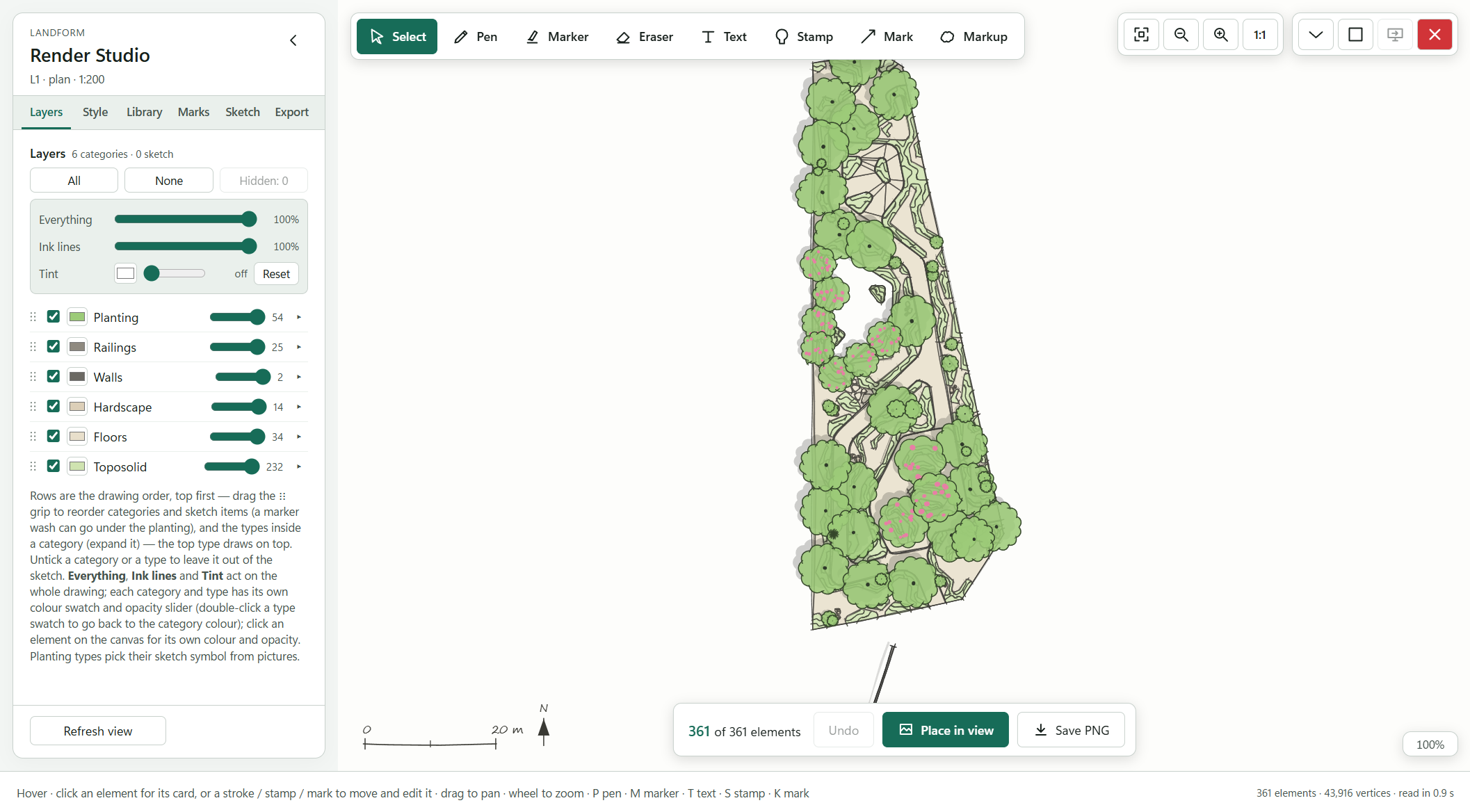
The panel header names the view that was read and its scale.
How many of the elements read from the view are in the sketch.
The six sidebar tabs, from drawing order to export settings.
Tick or untick every row at once; Hidden brings hidden elements back.
Act on the whole drawing; Reset restores the landscape palette.
Drawing order, top first. Drag the grip to reorder, untick to leave a category out, and set its colour swatch and opacity.
With Select, click an element to open its card for colour, opacity, symbol and hide options.
The mode bar for drawing over the sketch.
View controls; 1:1 shows the look the exports use.
Undoes the last stroke, mark or hide action.
Places the sketch in the active Revit view as an image.
Saves the drawing as a PNG at the size set on Export.
Reads the view again after model edits, keeping your layers, symbols and strokes.
Guidance for the current tool and its keyboard shortcuts.
Open LandForm tab → Analysis panel → Studios ▾ → Sketchy.
Wait for the read. A progress window reads the active view, then the workspace opens over the Revit drawing area with the view name in the panel header and the element count in the footer. The sidebar has six tabs: Layers, Style, Library, Marks, Sketch and Export.
Pick a style. On Style, choose a Preset: Marker sketch, Watercolour, Ink line, Pencil hatch or Digital (clean). Fine-tune Line wobble, Line weight, Pen passes, the Fill mode (Flat, Wash, Hatch or None) and Fill opacity.
Choose where colours come from with Colours (Landscape palette, Revit materials or Monochrome) and a Paper (White, Cream, Kraft, Grid or Transparent). Ink outlines on fills, Tree shadows with their Shadow angle and Length, and North arrow & scale bar can each be switched off.
Arrange the layers. On Layers, every category is a row in drawing order, top first. Drag the grip to reorder rows, expand a category to reorder or recolour its types, and untick a row to leave it out. Each row has its own colour swatch and opacity slider; double-click a type swatch to return to the category colour.
The Everything, Ink lines and Tint controls act on the whole drawing, and Reset restores the landscape palette. All and None tick every row at once.
Edit single elements. With the Select tool, click an element on the canvas to open its card. Set a colour and opacity for Type (every element of that type) or for This one, pick a planting Symbol for this type, or use Hide element, Hide type and Select in Revit. The Hidden button on the Layers tab brings hidden elements back.
Choose planting symbols. On Library, filter the gallery by style (trees, shrubs, xeriscape, grasses, tropical, formal, ground covers and more), pick a symbol and press Use for all planting, or let Auto by name read the family and type names (pine, palm, shrub and so on). Replace planting with symbols turns the replacement on and off; Prefer detailed trees and shrubs switches the automatic choice to the sketch-set drawings.
Under Import your own, Import from image… traces a picture of hand-drawn trees or shrubs into scalable symbols. Choose whether the drawings are used in sections & elevations or as plan symbols, then tick Prefer imported symbols and, if you like, Keep the sheet's colours.
Draw over the sketch. The mode bar on the canvas holds Select, Pen, Marker, Eraser, Text, Stamp, Mark and Markup. On Sketch, set the Pen style (Ink (pressure), Fineliner or Pencil), the Marker style (Flat marker, Chisel tip, Watercolour wash, Dry brush or Highlighter), the ink and marker colours and widths, and the Text size. Undo, Redo and Clear act on your strokes.
On Marks, drag a diagram chip (focal points, views, access, wind, screens, zone edges, notes) onto the drawing, or click it and then click on the canvas; drag for arrows and lines. Every stroke, stamp, mark and markup becomes a row on the Layers tab, so it can be reordered or deleted like a category.
Check the sketch at sheet scale. Use Fit, −, + and 1:1 in the view controls (top right). 1:1 shows the look the exports use. Press Tab to hide the sidebar and see more of the drawing.
Export or place. On Export, choose a PNG size and, if needed, Transparent background, then press Save PNG. To put the sketch into Revit, set Place at (px/m) and press Place in view; the same button sits on the bottom action bar. Save study… writes the style, layers, symbols and sketch to an .lfrender file that Load study… brings back later.
Refresh after model edits. Press Refresh view at the bottom of the sidebar to read the view again. Your layer settings, symbol choices and sketch strokes stay.
Nothing in the model has changed unless you pressed Place in view. That step writes the full drawing to a PNG and places it in the active view as an image, sized to the model, in one undo step named "LF-Render Studio: Place Sketch"; the image is selected afterwards so you can move or resize it like any other image. Saved PNGs render exactly what you see at the chosen size. Sketchy remembers its style, layer colours and symbol choices between sessions, and element-specific colours and the sketch strokes travel in the study file.
| Key | Action |
|---|---|
| V, P, M, E, T, S, K, R | Select, Pen, Marker, Eraser, Text, Stamp, Mark, Markup tools |
| Ctrl+Z / Ctrl+Y | Undo / redo strokes, marks and hide actions |
| Delete | Delete the selected sketch item, or hide the selected element |
| Esc | Cancel the current stroke, deselect, or return to the Select tool |
| Tab | Hide or show the sidebar |
| Home, + , − | Fit the drawing, zoom in, zoom out |
| F11 | Maximise the studio to full screen |
No separate LandForm window. This command runs directly from Revit selection and prompts; follow the workflow above and the messages shown beside the cursor or on Revit's status bar.

Analysis · Studios · Slope Analysis
Slope Analysis (the Slope Studio workspace) answers two questions at once: where will water sit, and where is the ground too steep for what it is meant to be? It loads every Floor and Toposolid of the model without you picking anything, grades each triangle of each top surface, and colours it green where it meets your rule, amber where it is too flat to drain and red where it is too steep. Contiguous patches outside the rule become findings you can zoom to and select in Revit. It is a checker only: the model is never changed, so you fix the ground with the terrain tools and reload to check again.
LandForm tab→Analysis panel→Studios ▾→Slope Analysis
Button tooltip: “Check every floor and toposolid against a grade rule.”Slope Analysis walkthrough. Until it is published, the steps and the annotated window below walk through the same workflow.
Numbers on the screenshot match the legend. Hover a number or a legend row to highlight the other.
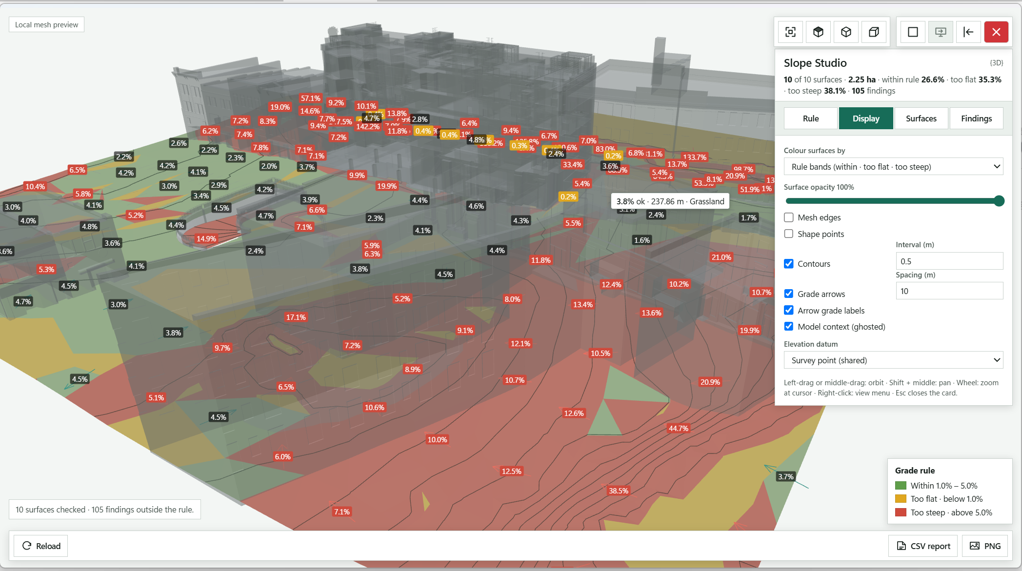
Summary of the surfaces checked, their area, the shares within the rule, too flat and too steep, and the number of findings.
Tabs for the grade rule, the Display options, the Surfaces list and the Findings list.
Every Floor and Toposolid coloured by the rule, with grade labels and downhill arrows; click a coloured patch to open its finding card.
The grade under the cursor, whether it is ok, too flat or too steep, the elevation and the surface name.
Zoom extents, Top, 3D and the Ortho toggle.
Orbit with the left or middle button, pan with Shift and the middle button, zoom with the wheel; right-click opens the view menu.
Legend for the colours: green within the rule, amber too flat, red too steep.
Counts the surfaces checked and the findings outside the rule.
Colours by Rule bands, a Grade heat map, Elevation or Plain; the slider sets Surface opacity.
Switches mesh edges, shape points, Contours with their Interval, Grade arrows with their Spacing, arrow labels and the ghosted model context.
Reads heights from the Survey point (shared) or the Revit internal origin.
Saves the per-surface areas and every finding; PNG saves the view.
Reads every surface again after you correct the model.
Open LandForm tab → Analysis panel → Studios ▾ → Slope Analysis.
Wait for the read. A progress window reads the floors and toposolids, then the workspace opens over the Revit drawing area with every surface coloured by the current rule. The summary at the top of the panel gives the surface count and the areas within, below and above the rule.
Set the rule. On the Rule tab pick a Preset (Accessible route · 1–5%, Paved area · 1–2%, Ramp · 5–8.3%, Lawn · 2–25%, Planting bed · 2–33%, Embankment · max 1:2 (50%) or Steep bank · max 1:1.5 (66.7%)) or type your own Minimum grade and Maximum grade. Grade units switches the whole studio between Percent (%), Ratio (1 : n) and Degrees (°).
Leave the minimum at 0 to check steepness only. Ignore findings smaller than drops patches below the area you enter (0.25 m² by default) so tiny facets do not clutter the list. The Totals table updates as you type.
Read the surfaces. Hover anywhere to see the grade under the cursor, whether it is ok, too flat or too steep, the elevation and the surface name. Orbit with the left or middle button, pan with Shift and the middle button, zoom with the wheel; the view controls at the top right give Zoom extents, Top, 3D and an Ortho toggle, and a right-click opens the view menu.
Open a finding. Click a coloured patch, or a row on the Findings tab, to open its card: too steep or too flat, the surface, its area, the worst grade against the rule, and the surface's category and type. Zoom frames the patch and Show in Revit selects its surface in the model.
On the Findings tab, Show limits the list to Too steep or Too flat, Sort orders by Largest first or Worst grade first, and Select surfaces with findings in Revit selects every offending surface at once.
Trim the set. On the Surfaces tab, untick a surface to leave it out of the analysis and the report (building floors, for instance), or use All, None, Toposolids only and Floors only. Each row shows the plan area and the share too flat and too steep; the eye button hides a surface from the view, R selects it in Revit, and clicking the row zooms to it. Hover a name for its level, point and triangle counts and any mesh repair that was applied.
Tune the display. On Display, colour surfaces by Rule bands, a Grade heat map, Elevation or Plain, and set Surface opacity. Switch Mesh edges, Shape points, Contours (with their Interval), Grade arrows (with their Spacing), Arrow grade labels and the ghosted Model context on or off. Elevation datum reads heights from the Survey point (shared) or the Revit internal origin.
Report and iterate. Press CSV report to save the per-surface areas and every finding, or PNG to save the view. Correct the model in Revit with Terrain Studio, the mound tools, Relax Surface or the Modify tools, then press Reload to read every surface again and check the result.
Nothing in the model has changed. You have a CSV with three blocks: one row per surface (name, element id, category, whether it was included, plan area, and the areas and percentages within the rule, too flat and too steep, plus the number of findings), the rule that was applied, and one row per finding with its surface, kind, area, lowest and highest grade and centre coordinates in metres. The PNG shows the coloured surfaces, arrows and labels as they were on screen. The rule you set is remembered the next time you open the studio.
No separate LandForm window. This command runs directly from Revit selection and prompts; follow the workflow above and the messages shown beside the cursor or on Revit's status bar.
LandForm ribbon panel
Legends, colour checks, exports and sheet set-up.

Documentation · Legend · Surface
Surface Legend is a studio window that sits over the Revit view while you work. You pick the surface types, decide which type parameters make up each item's text, tidy that text with clean-up rules, and arrange swatches and columns on a paper-space preview that wraps the text exactly as Revit will. You can even drop the legend onto a title block or an existing sheet to check that it fits before anything is created. When the layout is right, Run writes filled regions and text notes into an existing Revit Legend view, or renders a swatch image for each type and builds one schedule per category. Everything you chose is stored with the legend, so it can be reloaded, refreshed and kept in step with the model later.
LandForm tab→Documentation panel→Legend ▾→Surface
Button tooltip: “Create a floor and toposolid type legend.”Surface walkthrough. Until it is published, the steps and the annotated window below walk through the same workflow.
Numbers on the screenshot match the legend. Hover a number or a legend row to highlight the other.
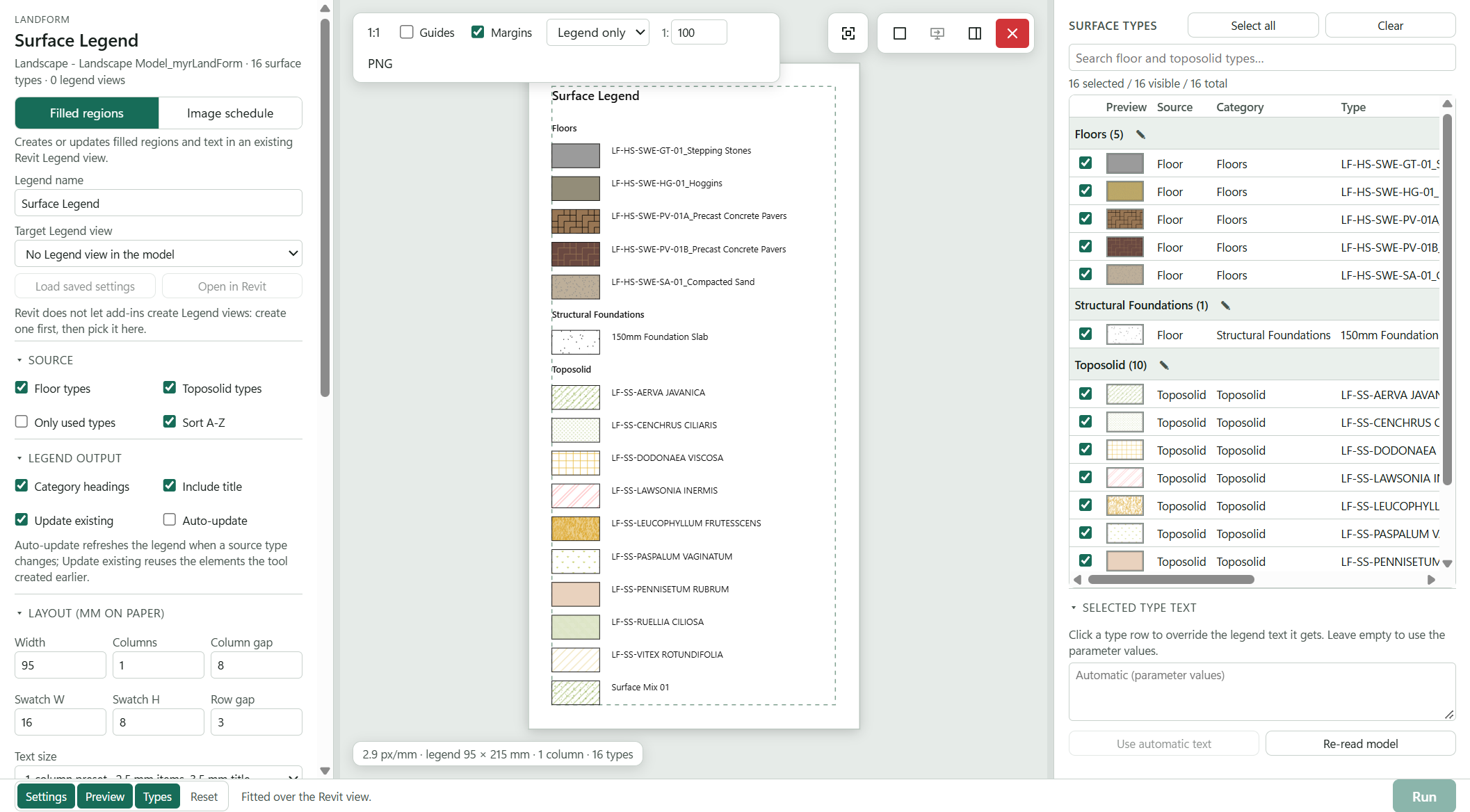
Chooses whether to write swatches and text into a Legend view or to build image schedules.
Names the legend and picks the existing Legend view to write into; Load saved settings restores a stored legend and Open in Revit activates the view.
Lists Floor and Toposolid types, optionally only the placed ones, sorted A-Z if you like.
Tick the types to include; the search box filters the list and Select all and Clear act on the visible rows.
Click a type row and type here to override its legend text; Use automatic text clears the override.
Category headings and title on or off; Update existing reuses earlier elements and Auto-update refreshes the legend when a source type changes.
Legend width, columns, column gap, swatch size, row gap and text size, all in paper millimetres.
1:1 zoom, Guides and Margins, the sheet menu (Legend only by default), the view scale and PNG to save the preview.
Draws every swatch in its real fill pattern, with the text wrapped as Revit will wrap it.
Reports the preview scale, legend size, columns and type count, and warns when the legend runs off the sheet.
Writes the legend into the target view, or builds the image schedules.
Shows progress and results, and tells you why Run is disabled.
Refreshes types, parameters and legend views from Revit without losing your settings.
Hide or show the panels; Reset shows every panel and fits the preview.
Open LandForm tab → Documentation panel → Legend ▾ → Surface.
Choose what to create. Press Filled regions or Image schedule at the top of the settings panel. Filled regions creates or updates swatches and text in an existing Legend view; Image schedule renders a swatch image for every type, assigns it as the type's Type Image and creates one schedule per Floor or Toposolid category.
Name the legend and pick the target view. Type the Legend name (it becomes the Legend view's name, or part of each schedule name). For filled regions choose the Target Legend view; views that already hold a LandForm legend are marked with a dot and show their scale. Load saved settings restores everything stored in that legend, and Open in Revit activates the view.
If you start the tool while a stored Surface Legend view is active, its settings load automatically and the status line says so.
Pick the surface types. Under Source, tick Floor types and Toposolid types as needed, Only used types to drop unplaced types and Sort A-Z to order by name. In the Surface types list on the right, tick the types to include. The search box filters the list, Select all and Clear act on the visible rows, and Shift-click ticks a range. The status line counts selected, visible and total types.
Build the item text. Under Legend item text, the chips are the parameters each type shows, in order. Drag a chip to reorder it, press its × to remove it, and click a parameter in the list below (filter it with Add a parameter…) to add it. The list tells you how many of the selected types have a value. Tick Join on one line with and enter a separator to combine the values into one line; type \n in the separator for a line break.
Clean up the text. Add a Find / Replace with rule, ticking the .\* box to treat Find as a regular expression. Strip code prefix removes everything up to and including the last underscore, so LF-HS-SWE-GT-01_Stepping Stones becomes Stepping Stones; Strip LF- code removes a leading letter code such as LF-SS-. Pick a Case option to force Title, Sentence, UPPER or lower case. Rules apply to automatic text only.
To give one type its own wording, click its row and type in Selected type text; Use automatic text clears the override. Double-click a category heading or the title in the preview, or press the pen beside a heading in the list, to rename it.
Set the layout. Under Layout (mm on paper) enter the legend Width, number of Columns and Column gap, the Swatch W and Swatch H, and the Row gap. Text size switches between the 1-column preset (2.5 mm items, 3.5 mm title), the 2-column preset (1.5 mm and 2 mm) and Custom…, which reveals Item text, Title text and Text width. Item text type and Title text type can use existing Text types instead of Automatic (by size). Advanced holds the Text offset between swatch and text and the Left and Top margin. Under Legend output, keep Category headings and Include title on or off, and use Update existing to reuse what the tool created earlier instead of adding to it.
Check the preview. The canvas draws every swatch with its real foreground and background fill pattern: drafting patterns at paper size, model patterns divided by the view scale in the 1: box, which follows the target view. Use Fit and 1:1, tick Guides for column guides and Margins to see the margin box, and press PNG to save the preview as an image. Choose a title block or an existing sheet from the sheet menu (the default is Legend only) to see the legend on paper with the sheet's existing viewports; drag the legend box into place or type its position in the at … × … mm boxes. The info line in the corner warns when the legend runs off the sheet.
Run. Press Run. For filled regions LandForm writes the swatches and text into the target Legend view in one undo step named "LF-Surface Legend: Generate Legend" and opens the view. For an image schedule it renders the images, assigns the Type Images and creates or updates the category schedules, reporting the counts in the footer.
Place it on sheets (optional). With a sheet chosen in the preview, press Place on sheet to put the target Legend view on that sheet at the dragged position; Sheets lets you tick several sheets, and every ticked sheet receives the legend at the same offset from its own title block. Tick on Run to place it automatically after every run.
For the filled-regions output, the target Legend view now holds a filled region per surface type in that type's own fill colours and patterns, the item text beside it, optional category headings and a title, laid out in the columns you set. Every element carries LandForm metadata, so running again on the same view replaces the earlier swatches instead of stacking a second legend, and Load saved settings brings back the parameters, rules and layout. For the image-schedule output, each selected type has a rendered swatch as its Type Image and each category has a schedule with the image column plus the fields you chose. The footer reports how many type rows, images and schedules were produced.
Creates or updates filled regions and text notes in an existing Revit Legend view.
Renders a swatch image per type, assigns it as the Type Image and creates one schedule per selected category.
Name for the target Legend view, or the stem of each category schedule name.
Existing Revit Legend view that receives the filled regions.
Lists Floor types as legend sources.
Lists Toposolid types as legend sources.
Keeps only types that have at least one instance placed in the model.
Orders the items by type name instead of model order.
Adds a heading row above each category group in the legend.
Adds the legend name as a title above the first row.
Reuses the legend elements or schedules the tool created earlier instead of adding new ones.
Registers the legend for automatic refresh when a source type changes.
Shows the paper-space layout values: width, columns, gaps, swatch size, text offset and width, text preset and sizes, margins.
1 column (2.5 mm items, 3.5 mm title), 2 columns (1.5 mm and 2 mm) or Custom sizes.
Pixel size of each rendered swatch image: 256, 512 or 1024 px.
Replaces Type Images that already exist instead of keeping them.
Shows the parameters that make up each item's text and how they are joined.
Filters the parameter list by name.
Joins the parameter values on one line with the separator instead of one line per value.
Moves the selected parameter earlier in the item text.
Moves the selected parameter later in the item text.
Includes this parameter in the legend text.
Text placed between combined parameter values.
Inserts a line break into the separator so the next value starts a new row.
Ticks every parameter currently shown by the search.
Unticks every parameter currently shown by the search.
Draws the legend layout with the current settings without changing the model.
Collapses or restores the settings column so the type list gets the full width.
Ticks only the types that have no Type Image yet (image schedule mode).
Ticks every visible surface type.
Unticks every visible surface type.
Search Floor Types and Toposolid Types by name.
Chooses, orders and renames the schedule fields for that category.
Creates the legend or the image schedules with the current settings.
Closes Surface Legend without changing the model.

Documentation · Legend · Family
The Family legend studio reads a sheet for you: every family type visible in the views and schedules placed on it is listed by category with its instance count, so you never have to hunt for what needs a key. Choose Image schedule to render a plan symbol for each type, store it as the type's Type Image and build a schedule that shows it, or Model legend to create Revit legend views from a template Legend Component, grouped and scaled to fit. A live preview in the middle shows the schedules or the legend as you change the settings.
LandForm tab→Documentation panel→Legend ▾→Family
Button tooltip: “Create a family legend from a sheet.”Family walkthrough. Until it is published, the steps and the annotated window below walk through the same workflow.
Numbers on the screenshot match the legend. Hover a number or a legend row to highlight the other.
Chooses the approach; the hint beneath explains what each one produces.
The sheet whose placed views and schedules supply the family types; type to filter a long list.
The legend view whose Legend Component sets the view direction and graphics for every symbol.
Opens the template legend to check it, or refreshes the lists after you change something in Revit.
Filters the list, selects only types with no Type Image yet, or selects or clears everything.
Every type by category with its 3D thumbnail, instance Count and Image state; tick types or whole categories.
Each selected category gets its own box for columns, grouping and sorting, or label values for a model legend.
Symbol, Image size, Line weight, whether to Regenerate existing Type Images, and Keep PNG copies in a folder.
One schedule per category, its Title text and Title layout, and what happens to Existing schedules.
Shows the schedules or the legend as you change the settings.
Progress and the run summary appear here in the footer.
Generates the images and schedules, or creates the legend, with the current settings.
Hide or show each panel of the studio; Reset brings them all back.
Open LandForm tab → Documentation panel → Legend ▾ → Family.
Choose the approach. Press Image schedule or Model legend at the top of the settings panel. The hint beneath explains what each one produces.
Pick the sheet and template. Choose Source sheet (type in Find a sheet… to filter a long list) and the Template legend that holds the Legend Component. Open in Revit opens the template legend so you can check it; Re-read model refreshes the lists after you change something in Revit.
Select the family types. The Family types on the sheet list on the right shows every type by category with its 3D thumbnail, instance Count and Image state. Tick types or whole categories, search with Search family or type…, or press Missing only to select just the types that have no Type Image yet. All and None select or clear everything.
Set up each category. Under Per category, each selected category gets its own box. For an image schedule, choose the columns (field and optional heading), reorder them with the arrow, strip type-name prefixes such as LF-PL-, and set Group rows by, A–Z, Group header and Blank line between groups. For a model legend, tick the label values shown under each symbol in order, set the Separator and the Grouping parameter.
Image schedule settings. Under Images, choose the Symbol (Legend symbol (plan) or 3D family preview), Image size and Line weight, and decide whether to Regenerate existing Type Images and Keep PNG copies in a folder. Under Schedules, set the Title text, Title layout, what happens to Existing schedules, which prefixes to strip from headings, and whether to show Bold title and headers and a Count column.
Model legend settings. Under Legend, enter the Legend name, the number of Columns, how to Group and scale by and the Max scale groups, and choose sorting, Include title, Instance counts, Place on the source sheet and Auto-update labels.
Check the preview and run. The middle panel previews the schedules or the legend; family and type names are shown, other parameter values appear as their name in brackets until Revit fills them in. Press the button at the bottom right, which reads Generate images + schedules, Generate images or Create legend. Progress and the summary appear in the footer.
With Image schedule, each selected type has a plan-symbol (or 3D) image assigned as its Type Image, or to the LF_Type Image parameter where the built-in Type Image cannot be set, and each selected category has a schedule named from your title text that shows the image beside the chosen columns. With Model legend, one or more Revit legend views are created from the template Legend Component, one per group at a scale that suits its symbols, and arranged on the source sheet if you asked for it; otherwise Revit opens the new legend. The legend is created in one undo step named "LF-Family Legend: Create Legend", and the footer summary lists the scales used and any types that were skipped.
LF_Type Image), Unavailable, or Black background for an older image that Revit shows on black; running again renders those on white.Renders a plan symbol for each selected type, assigns it as the Type Image and builds one schedule per category.
Creates Revit legend views from the template legend, grouped and scaled to fit, and can place them on the source sheet.
The sheet whose placed views and schedules supply the family types.
Filters the sheet list by sheet number or name.
The legend view whose Legend Component sets the view direction and graphics for every symbol.
Opens the template legend in Revit.
Reads the sheets, legends and family types from Revit again, keeping your settings.
Legend symbol (plan) renders the plan symbol through the template; 3D family preview uses the family's 3D thumbnail.
Size of each rendered image: 256, 512 or 1024 px.
How heavy the symbol lines are in the image: as in the views, bold, extra bold or hairline.
Renders and replaces images that are already assigned instead of keeping them.
Also saves every rendered image as a PNG file in the output folder.
Folder for the PNG copies.
Chooses the folder for the PNG copies.
Builds a schedule for each selected category; turn it off to only generate images.
Text used in the schedule titles.
Category + title, title + category, or the exact title text.
Update the schedule with the matching name, or create a new one.
Comma-separated prefixes removed from the visible column headings.
Sets the schedule title and column headers in bold.
Adds a Count column with the number of placed instances.
Name of the legend view to create.
Number of columns the legend items are arranged in.
The most scale groups, and so legend views, that grouping by displayed size may create.
Category, a type parameter per category, displayed size, or no grouping (one legend at the template scale).
Orders the legend by category before the label text.
Sorts the legend items A to Z; off sorts Z to A.
Adds the legend name as a title.
Adds the number of placed instances after each label.
Arranges the finished legend views on the source sheet.
Keeps the legend text and counts in step with later changes to the source types and instances.
Filters the family type list.
Selects only the types that have no Type Image yet.
Selects every family type on the sheet.
Clears the type selection.
Every legendable family type on the sheet, by category, with 3D thumbnail, instance count and image state.
Adds another schedule column for that category.
The parameter the category's schedule rows are grouped and sorted by.
Shows a heading row for each group in the schedule.
Adds an empty row between schedule groups.
Text placed between the label values in a model legend.
The type parameter used to group this category when grouping by type parameter.
Hide or show each panel of the studio.
Shows all three panels again.
Generates the images and schedules, or creates the legend, with the current settings.

Documentation · Legend · Filter
Filter legends are tedious to draw by hand and go stale the moment someone changes a colour. The Filter legend studio reads the filters assigned to a view or template, shows each one with the fill pattern and colours it actually applies, and previews the finished legend on paper at its real size in millimetres. When the layout looks right, one click builds the legend as Filled Regions and text notes in a drafting view, ready to place on a sheet.
LandForm tab→Documentation panel→Legend ▾→Filter
Button tooltip: “Create a legend from view-filter graphics.”Filter walkthrough. Until it is published, the steps and the annotated window below walk through the same workflow.
Numbers on the screenshot match the legend. Hover a number or a legend row to highlight the other.
Click the view whose filters you want; Only views hides view templates and Find a view… filters a long list.
Opens the selected source view in Revit.
The source's filters with their swatch and state; ticked filters become legend rows. All and None select or clear them, Find a filter… narrows the list.
Add a title, the Title text, Append the source view name, and the Column headers and Status notes switches.
Region types creates one reusable Filled Region type per filter graphic; View overrides draws plain regions coloured only in the legend view.
Legend width, margins, swatch size, row gap, text offset and width, and the three text sizes, all in mm on paper.
Defaults puts every layout and title value back; Re-read model reads the views, templates and filters from Revit again.
The legend on paper at its real size; it updates as you type. Scroll to zoom and drag to pan.
Shows the whole legend in the preview.
100% shows the preview at 1 mm = 4 pixels; PNG saves the preview as an image.
The legend size in millimetres and the row count.
Builds the legend drafting view from the ticked filters and opens it; the footer line beside it reports the filter rows.
Hide or show each panel of the studio; Reset brings all three back and refits the preview.
Open LandForm tab → Documentation panel → Legend ▾ → Filter.
Choose the source. In Source view or template on the right, click the view whose filters you want to document. Leave Only views on to list regular views, or turn it off to include view templates; type in Find a view… to filter a long list. Open in Revit opens the selected view.
Select the filters. Assigned filters lists every filter of the source with its swatch and state (Visible, Hidden or Disabled). All of them start selected; untick the ones to leave out, or use All and None. Find a filter… narrows the list.
Set the title. Under Title, keep Add a title on and enter the Title text. Append the source view name adds the view name to the title. Turn Column headers and Status notes on or off.
Choose the swatch type. Under Swatches, pick Region types to create one reusable Filled Region type per filter graphic, or View overrides to draw plain regions coloured only inside the legend view.
Adjust the layout. Under Layout (mm on paper), set the legend Width, margins, swatch size, Row gap, text offset and width, and the three text sizes. The preview in the middle updates as you type; Defaults puts every value back.
Check the preview. Scroll to zoom and drag to pan the preview. Fit shows the whole legend, 100% shows it at 1 mm = 4 pixels, and PNG saves the preview as an image. The card in the bottom corner shows the legend size in millimetres and the row count.
Create the legend. Press Create legend. Revit opens the new drafting view and the footer reports how many filter rows were generated.
A drafting view named after the source view now holds the legend: an optional title, optional column headers, and for each selected filter a Filled Region swatch with the filter's fill pattern, colours and line colour, plus a text note with its name and any status notes. With Region types the swatches use Filled Region types you can reuse elsewhere; with View overrides they are plain regions overridden in this view only. The whole legend is one undo step named "LF-Filter Legend: Create Legend", and the drafting view can be placed on any sheet like a normal view.
Places a title text at the top of the legend.
The legend title; empty uses "Filter Legend".
Adds the source view name to the title.
Adds the Surface and Filter column headings above the rows.
Adds Disabled, Hidden, transparency and halftone notes under a filter's name.
Creates one reusable Filled Region type per filter graphic.
Draws plain regions and colours them with overrides in the legend view only.
Overall legend width on paper, in mm.
Space to the left of the swatches, in mm.
Space above the title, in mm.
Swatch width, in mm.
Swatch height, in mm.
Vertical space between rows, in mm.
Gap between a swatch and its text, in mm.
Width of the filter name text, in mm; longer names wrap.
Space between the column headers and the first row, in mm.
Text size of the filter names, in mm.
Text size of the column headers, in mm.
Text size of the title, in mm.
Restores the LandForm default layout and title settings.
Reads the views, templates and filters from Revit again.
Fits the whole legend in the preview.
Shows the preview at 1 mm = 4 pixels.
Saves the preview as a PNG image.
Filters the source list by view name or view type.
Lists only regular views; turn it off to include view templates.
Views and templates that carry filters, with their kind and filter count. Double-click one to create its legend.
Opens the selected source view in Revit.
Filters the assigned filter list by name or state.
Selects every assigned filter.
Clears the filter selection.
The source's filters with their swatch and state; ticked filters become legend rows.
Hide or show each panel of the studio.
Shows all three panels again and refits the preview.
Builds the legend drafting view from the selected filters and settings.

Documentation · Color Splash
Color Splash is the fastest way to see how a model is made up: which floors use which build-up, which planting carries which botanical name, which toposolids are still unassigned. You pick a category and a parameter, LandForm lists every value it finds in the view with a count and a colour, and one click paints the view. Choose Apply colors for a quick check, or Create filters when the colouring should stay in the view, travel with a view template and appear in Visibility/Graphics.
LandForm tab→Documentation panel→Color Splash
Button tooltip: “Color visible elements by a parameter value.”Color Splash walkthrough. Until it is published, the steps and the annotated window below walk through the same workflow.
Numbers on the screenshot match the legend. Hover a number or a legend row to highlight the other.
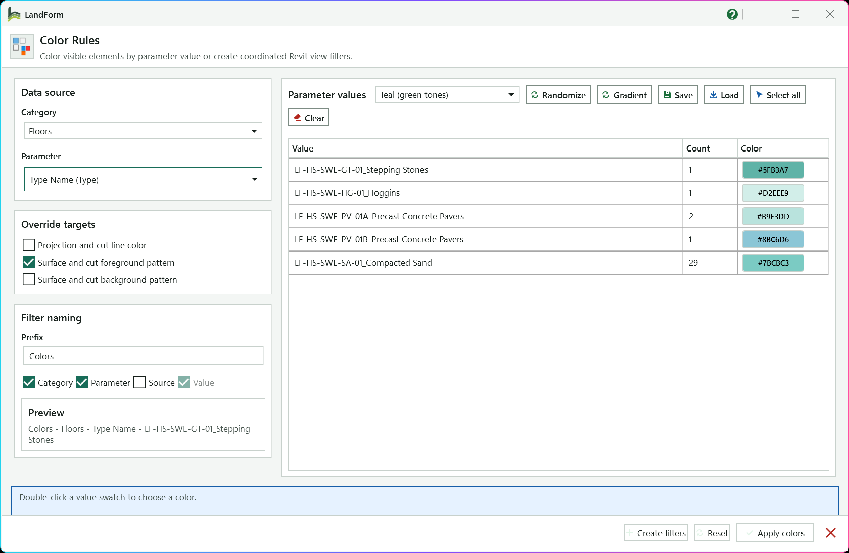
The model category to colour; only categories visible in the active view are listed.
The instance or type parameter whose values set the colours; type to narrow the list.
Every value found in the view with its element count and colour; double-click a row to choose its colour.
The colour palette; changing it recolours every value.
Recolour from the palette, or blend evenly from the first colour to the last.
Store the current colours as a scheme, or apply a saved scheme so the same values get the same colours.
Choose whether lines, foreground fills and/or background fills take the colour.
The text and name parts used to build each filter name.
Shows the first filter name as it will be created.
Colours the listed elements with element overrides in this view only.
Builds or updates one view filter per value and adds it to the active view.
Selects every listed element in Revit so you can inspect them.
Removes this category's colour filters from the view and the project, and clears the element overrides.
Shows guidance for the next step.
Open LandForm tab → Documentation panel → Color Splash.
Open the right view. Make the plan, section or 3D view you want to colour the active view, then start Color Splash.
Choose the data. Pick the Category, then the Parameter. Type part of a parameter name in the box to narrow the list. The value table fills with every value found in the view and how many elements carry it.
Set the colours. Pick a palette from the list above the table. Double-click any row to choose its colour by hand, press Gradient to blend from the first colour to the last, or Randomize to start again from the palette.
Load applies a saved scheme so the same values get the same colours on every drawing; Save stores the current colours for next time.
Choose what gets coloured. Under Override targets, tick Projection and cut line color, Surface and cut foreground pattern and/or Surface and cut background pattern. The foreground pattern alone gives the familiar solid colour fill.
Colour the view. Press Apply colors for element overrides in this view only. Or set the Prefix and name tokens under Filter naming, check the Preview, and press Create filters to build one view filter per value.
Check and adjust. Look at the view, change a colour and press the same button again to update it. Press Select all to select every listed element in Revit if you want to inspect them.
Remove the colouring (optional). Press Reset to remove the colour filters of the current category and parameter from the view, delete them from the project, and clear the element overrides on that category.
With Apply colors, every listed element in the active view carries a graphic override in its value's colour; nothing outside this view changes. With Create filters, the project gains one rule-based view filter per value (for example "Colors - Floors - Type Name - LF_Paving"), each added to the active view with its colour override, so the colouring shows in Visibility/Graphics and can be copied to a view template. Each button is one undo step: "LF-Color Rules: Apply Overrides", "LF-Color Rules: Create Filters" or "LF-Color Rules: Reset Overrides".
Model categories that have elements visible in the active view. Choosing one reloads the parameters and values.
Instance and type parameters of the category; type to search. Type Name is selected by default.
Applies the value colour to projection and cut lines.
Applies the value colour as a solid foreground fill on surfaces and cuts.
Applies the value colour as a solid background fill on surfaces and cuts.
Text at the start of every filter name; empty uses "Colors".
Adds the category name to the filter names.
Adds the parameter name to the filter names.
Adds Instance or Type to the filter names.
A value token is required so every generated filter name remains unique.
The colour palette; changing it recolours every value.
Recolours every value from the selected palette, replacing hand-picked colours.
Blends the colours evenly from the first value to the last. Needs at least two values.
Saves the value colours to a Color Rules scheme file (.cschn).
Loads a scheme file and applies its colours by matching value or by row position.
Selects every element in the value list in Revit.
Clears the Revit selection.
Each value with its element count and colour; double-click a row to choose its colour.
Creates or updates one view filter per value and adds it to the active view with that colour.
Removes this category's colour filters from the view, deletes them from the project and clears the element overrides on its elements.
Applies the colours to the listed elements as element overrides in the active view.

Documentation · Export · Document Export
Document Export replaces the round of separate Print, Export DWG and Export NWC dialogs that a drawing issue normally takes. Everything printable in the project is listed in three tabs; you tick Export on the rows you need, add PDF, DWG, DWF, DWFx, NWC or IFC per row, and press Export package. Along the way you can filter by a Revit sheet set or Sheet List schedule, build file names from any sheet or view parameter, add or remove a project revision on the selected sheets, save the selection as a new Revit sheet set, and write a transmittal CSV that lists what was issued. The window is modeless, so you can keep working in Revit while it is open, and all of its settings are remembered between sessions.
LandForm tab→Documentation panel→Export ▾→Document Export
Button tooltip: “Export coordinated sheets and views.”Document Export walkthrough. Until it is published, the steps and the annotated window below walk through the same workflow.
Numbers on the screenshot match the legend. Hover a number or a legend row to highlight the other.
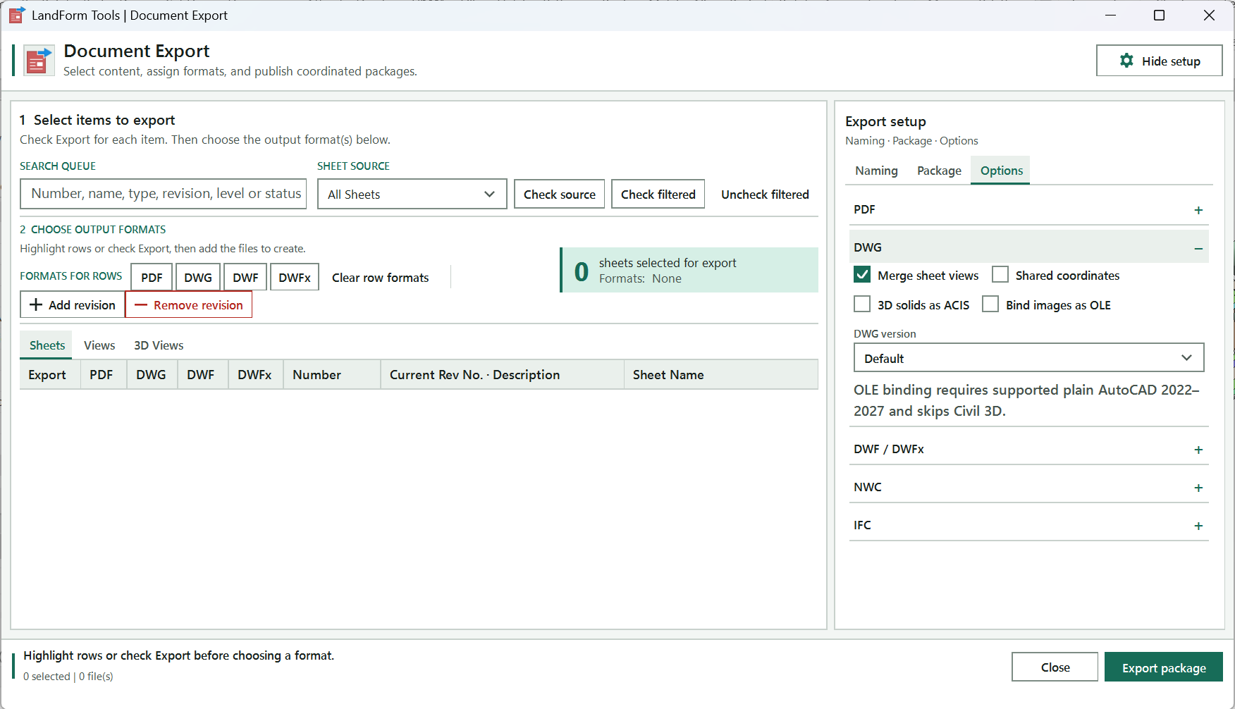
Filters the active tab by number, name, type, revision, scale, level or status.
Shows all sheets, a saved sheet set or the sheets of a Sheet List schedule.
The three lists of printable items; Views and 3D Views load the first time you open them.
Ticks the sheets of the chosen source, or ticks or clears Export on every visible row.
One row per item with its Export tick and a tick per format; highlight several rows to change them together.
PDF, DWG, DWF and DWFx switch a format on or off for the highlighted rows, or the checked rows when none are highlighted.
Removes every format from the target rows and keeps their Export ticks.
Opens the revision picker to add a project revision to, or remove one from, the highlighted or checked sheets.
How many items are selected for export and which formats they carry.
Reveals the Naming, Package and Options tabs.
Checks the folder, selection and formats, then writes every file.
Shows the selection and file count, and the progress of a running export.
Open LandForm tab → Documentation panel → Export ▾ → Document Export.
Find the rows you need. Type in the SEARCH QUEUE box to filter the active tab by number, name, type, revision, scale, level or status; several words narrow the list further. On the Sheets tab, pick a saved sheet set or a Sheet List · <schedule> entry under SHEET SOURCE to show only those sheets.
Check Export. Tick Export on each row, or use Check filtered to tick every visible row and Uncheck filtered to clear them. Check source ticks exactly the sheets in the selected sheet set or Sheet List schedule and unticks the rest.
Tick a box while several rows are highlighted and the same change is applied to all of them.
Assign formats. Highlight rows (or rely on the checked rows) and press PDF, DWG, DWF or DWFx under FORMATS FOR ROWS to switch that format on; press again to switch it off. On the 3D Views tab the buttons are DWG, DWF, DWFx, NWC and IFC. You can also tick the individual format columns in the grid. Clear row formats removes every format from the target rows. The counter on the right shows how many items are selected and which formats they carry.
Open the setup panel. Press Show setup in the header to reveal the Naming, Package and Options tabs.
Set file naming. On Naming, the default rule is <Sheet Number>-<Sheet Name> for sheets and <Type>-<View Name> for views. Press Edit sheet or Edit view next to PDF, DWG or DWFx to open the naming-rule editor, where you add parameters, type a prefix, suffix and separator for each, reorder them and watch the preview. Save a set of rules as a preset with Save so you can switch between office standards with the preset list.
Set the package. On Package, choose the Output folder, and tick Create subfolders from Project Browser organization if the files should land in folders that match the browser tree. Optionally type a name and press Create from selected sheets to store the checked sheets as a Revit sheet set, pick a revision (or New revision... with a description and date) and press Add to selected sheets, and decide whether to Create transmittal CSV with the title, project, dates, recipient, format and copies it should record.
Review format options. On Options, expand PDF, DWG, DWF / DWFx, NWC or IFC to adjust the export settings for each format: hidden planes and boxes for PDF, merged views, shared coordinates and DWG version for DWG, the coordinate system and included data for NWC, the schema and view filter for IFC.
Export. Press Export package. If Bind images as OLE or Shared-coordinate sheet XREFs is on, LandForm first confirms that AutoCAD will be used. The footer shows a progress bar and the item being written; the close button becomes Cancel and stops the run after the current file. A completion dialog lists how many files were written, where, and anything that was skipped.
The output folder holds one file per checked item per format, named by the rule for that format, plus the transmittal CSV if you asked for one. PDF files are combined per sheet or view, fitted to the page, in colour. In a workshared model, DWG files are exported with temporary type worksets so the layers are split by Revit type; the worksets are rolled back as soon as the export finishes and the model is left unchanged. Only three actions touch the model, and each is a single undoable step: "LF-Document Export: Create Sheet Set", "LF-Document Export: Add Revision" and "LF-Document Export: Remove Revision". The status line and the completion dialog confirm the file count and folder.
| Format | Applies to | What is written |
|---|---|---|
| Sheets, views | One combined PDF per item, fit to page, centred, colour, high raster quality. | |
| DWG | Sheets, views, 3D views | One DWG per item in the chosen DWG version; sheets can keep merged views, native shared coordinates or shared-coordinate XREFs. |
| DWF / DWFx | Sheets, views, 3D views | One DWF or DWFx per item, with merged views and optional crop box, object data, textures and rooms. |
| NWC | 3D views only | One Navisworks cache per 3D view in Shared or Internal coordinates. |
| IFC | 3D views only | One IFC file per 3D view in the chosen IFC version, optionally limited to what the view shows. |
| Transmittal CSV | Package | A record sheet listing number, revision, name, scale and paper size for every exported item, plus the recipient. |
The + / − header on each group of the Options tab. Click it to expand or collapse that format's settings.
Shows or hides the Export setup panel with the Naming, Package and Options tabs. Reads Show setup or Hide setup.
Filters the active tab by sheet number, view name, type, revision, scale, level or status. Several words must all match.
Limits the Sheets tab to All Sheets, a saved Revit sheet set, or the sheets in a Sheet List schedule.
Ticks Export on exactly the sheets in the selected sheet set or Sheet List schedule and unticks the rest. With All Sheets it ticks every visible sheet.
Ticks Export on every row currently shown by the filter in the active tab.
Removes the Export tick from every row currently shown by the filter in the active tab.
Switches PDF on for the highlighted rows, or for the checked Export rows when none are highlighted; press again to switch it off. Hidden on the 3D Views tab.
Switches DWG on or off for the highlighted rows, or for the checked Export rows when none are highlighted.
Switches DWF on or off for the highlighted rows, or for the checked Export rows when none are highlighted.
Switches DWFx on or off for the highlighted rows, or for the checked Export rows when none are highlighted.
Switches NWC on or off for the highlighted 3D view rows, or for the checked ones when none are highlighted. Shown on the 3D Views tab only.
Switches IFC on or off for the highlighted 3D view rows, or for the checked ones when none are highlighted. Shown on the 3D Views tab only.
Removes every format from the highlighted rows, or from the checked Export rows when none are highlighted. Export ticks are kept.
Opens the revision picker so you can add an existing project revision to the highlighted sheets, or to the checked Export sheets. Sheets tab only.
Opens the revision picker so you can remove a manually assigned revision, or all of them, from the highlighted or checked sheets. Sheets tab only.
Lists every printable sheet with its number, current revision and name.
One row per sheet with Export and format ticks. Highlight several rows to change them together.
Includes this sheet in the export.
Writes a PDF for this row.
Writes a DWG for this row.
Writes a DWF for this row.
Writes a DWFx for this row.
Lists every printable 2D view with its type, name, scale and level. Loads when first opened.
One row per view with Export and format ticks.
Includes this view in the export.
Lists every 3D view (orthographic and perspective) with its status. Loads when first opened.
One row per 3D view with Export, NWC, DWG, DWF, DWFx and IFC ticks.
Includes this 3D view in the export.
Writes a Navisworks NWC for this 3D view.
Writes an IFC file for this 3D view.
Holds the naming presets and the per-format file naming rules.
Loads a saved naming preset. Its rules replace the current PDF, DWG and DWFx rules.
Name under which Save stores the current rules. Saving with an existing name overwrites that preset.
Saves the current naming rules as a preset with the typed name.
Deletes the selected naming preset. At least one preset must remain.
Opens the naming-rule editor for PDF files of the active tab (sheets or views).
Opens the naming-rule editor for DWG files of the active tab (sheets or views).
Opens the naming-rule editor for DWFx files of the active tab (sheets or views). DWF, NWC and IFC use the default rule.
Holds the output folder, sheet set, revision and transmittal settings.
Opens a folder picker for the output folder.
Folder the files are written to. Created if it does not exist.
Saves each file into subfolders that match the sheet or view organisation in the Project Browser. Items without a matching folder go to the root.
Name for the Revit sheet set created from the checked sheets. A number is appended if the name already exists.
Creates a Revit sheet set containing the checked sheets, so the same selection can be used in Print and in SHEET SOURCE later.
Chooses New revision... or an existing project revision to add with Add to selected sheets.
Description for a new revision. Required when New revision... is selected.
Date text for a new revision.
Marks a new revision as issued when it is created.
Adds the chosen revision to every checked sheet, creating it first if New revision... is selected.
Writes a transmittal record CSV into the output folder at the end of the export.
Title line of the transmittal record and its file name.
Project name written to the transmittal. Defaults to the Project Information name or the file name.
Transmittal date written to the record. Defaults to today.
Report date written to the record. Defaults to today.
Contact name written at the end of the transmittal.
Delivery format code written next to the recipient, for example C.
Number of copies written next to the recipient. Whole numbers only.
Holds the export settings for each format.
Settings applied to every PDF written.
Leaves reference and work planes out of the PDF.
Leaves scope boxes out of the PDF.
Leaves crop boundaries out of the PDF.
Leaves view tags that reference no sheet out of the PDF.
Prints view references in blue so they stand out as links.
Replaces halftone lines with thin lines.
Masks edges that coincide so they are not drawn twice.
Always uses raster processing for the PDF.
Stops the PDF export at the first error instead of continuing.
Settings applied to every DWG written.
Experimental, sheet DWGs only. Keeps each paper-space viewport, exports its plan view as a shared-coordinate XREF and uses AutoCAD in the background to restore the viewport's centre and scale. Needs AutoCAD 2022 to 2027.
Exports the views on a sheet into one DWG instead of one XREF per view.
Uses Revit's own shared-coordinate export for the DWG geometry.
Exports 3D solids as ACIS solids rather than polymesh.
Opens plain AutoCAD after each DWG to convert raster image references into embedded OLE objects. Civil 3D is skipped.
DWG file version: Default, R2018, R2013, R2010 or R2007.
Settings applied to DWF and DWFx files.
Exports the views on a sheet into one DWF or DWFx.
Keeps the crop box visible in the DWF or DWFx.
Includes element properties in the DWF.
Includes material textures in the DWF.
Includes rooms and areas in the DWF.
Settings applied to every Navisworks NWC written.
Exports the NWC in Shared or Internal coordinates.
Converts linked CAD files into the NWC.
Includes element properties in the NWC.
Splits the NWC by level.
Searches for missing materials when writing the NWC.
Includes room geometry in the NWC.
Includes linked Revit models in the NWC.
Writes Revit element IDs into the NWC.
Settings applied to every IFC file written.
IFC schema: Default, IFC4, IFC4RV, IFC4x3, IFC2x3, IFC2x3CV2 or IFC2x3FM.
Exports only the elements visible in the 3D view, using the view's geometry.
Writes base quantities into the IFC.
Splits walls and columns at each level in the IFC.
Space boundary level 0, 1 or 2 for the IFC.
Validates the folder, selection and formats, confirms any AutoCAD step, then writes every file and the transmittal.
Closes the window, or cancels the running export after the current file when an export is in progress.
Filters the list of available sheet or view parameters; several words must all match.
Clears the parameter search so the whole list is shown again.
Sheet or view parameters you can add to the file name, including every parameter found on the project's sheets or views.
Appends the selected parameter to the naming rule. The first part gets a - separator.
The parts of the file name in order. Type a Prefix, Suffix and Separator for each; Sample shows the value from the first sheet or view.
Moves the selected part one place earlier in the file name.
Moves the selected part one place later in the file name.
Removes the selected part from the rule.
Applies the rule to the format and tab it was opened for. Parts with an empty value are skipped at export time.
Project revisions with number, description, date and issued state. Double-click a row to choose it.
Removes every manually assigned revision from the target sheets. Revisions controlled by revision clouds remain. Shown when removing.
Labelled Run. Adds or removes the selected revision on the target sheets in one undoable step.

Documentation · Export · Sheet Shared DWG
Revit's own sheet DWG export writes model geometry at project-internal coordinates, which is useless to anyone who needs to drop your sheet onto a coordinated base. Sheet Shared DWG exports each sheet's paper space as normal, exports every plan viewport on it again as a separate shared-coordinate DWG, then runs AutoCAD in the background to attach those drawings as XREFs and restore each viewport's Revit centre, scale and rotation. The title block and sheet annotation are never touched. Use it only when coordinated model space must be shared; for ordinary sheet output, several formats at once or plotted-sheet delivery, use Document Export.
LandForm tab→Documentation panel→Export ▾→Sheet Shared DWG
Button tooltip: “Experimental DWG-only export. Use only when shared-coordinate model space is required.”Sheet Shared DWG walkthrough. Until it is published, the steps and the annotated window below walk through the same workflow.
Numbers on the screenshot match the legend. Hover a number or a legend row to highlight the other.
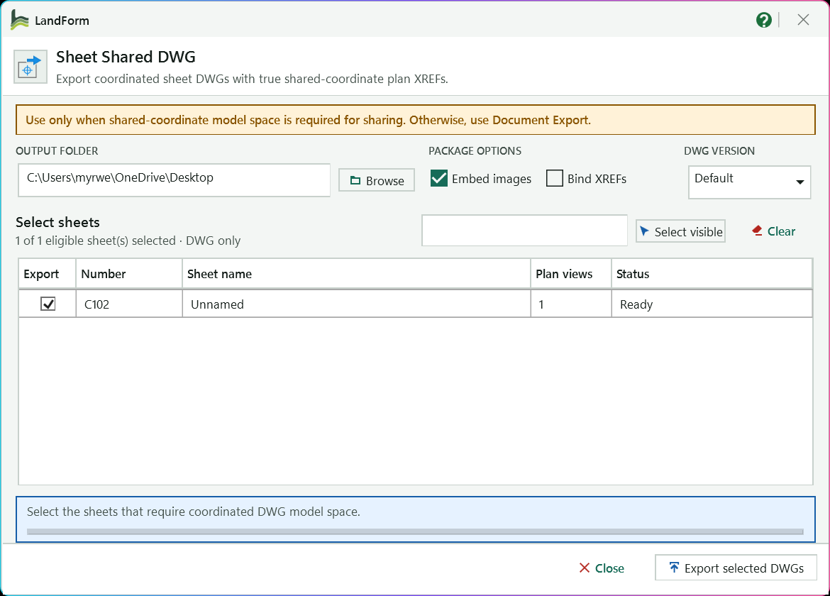
A reminder to use this tool only when shared-coordinate model space must be shared; use Document Export otherwise.
The folder for the sheet DWGs, their XREF files and the logs; remembered for next time.
Converts raster image references into embedded OLE objects using plain AutoCAD.
Binds the plan drawings into the sheet DWG as blocks, so one file carries everything.
Pick an older DWG format if the recipient needs one.
Filters the sheet list by number or name.
Ticks every filtered sheet, or unticks everything.
Tick Export per sheet; Plan views shows how many shared-coordinate XREFs it will produce and Status reports progress.
How many eligible sheets are ticked.
Confirms the summary, then exports each ticked sheet and runs the AutoCAD correction.
Guidance before the run, then each sheet and view being written.
Closes the window; during an export it becomes Cancel and stops after the current safe step.
Open LandForm tab → Documentation panel → Export ▾ → Sheet Shared DWG.
Choose where the package goes. Type or Browse to the OUTPUT FOLDER. The folder and the options below are remembered for next time.
Set the package options. Tick Embed images to convert raster image references in the sheet and its XREFs into embedded OLE objects (AutoCAD opens briefly for each file). Tick Bind XREFs if the recipient should get a single self-contained sheet DWG with the plan drawings bound in as blocks. Pick a DWG VERSION if the recipient needs an older format.
Select the sheets. Tick Export on each sheet, or type part of a number or name in the search box and press Select visible to tick every filtered row. Clear unticks everything. The Plan views column tells you how many shared-coordinate XREFs each sheet will produce, and the summary above the list reads N of M eligible sheet(s) selected · DWG only.
If the active view is a sheet, that sheet is ticked when the window opens.
Export. Press Export selected DWGs and confirm the summary, which repeats how many sheets will be exported and which post-processing steps are on. The Status column changes to Exporting, then Embedding images when that option is on, while the footer reports each sheet and view being written and the AutoCAD correction.
Press Cancel in the footer to stop after the current safe step; drawings already completed are kept and the sheet being processed keeps its plain Revit export.
Read the completion report. The final dialog tells you how many sheet packages were corrected, how many XREF files they reference, how many DWGs had their images embedded, and lists the first warnings. Each sheet row now reads Corrected · 2 XREF(s) (with · bound and · OLE when those options were used), Plain DWG when the sheet had no plan viewport to re-reference, or Plain DWG retained when the AutoCAD step failed.
For every selected sheet the output folder holds <Number> - <Name>.dwg, one <Number> - <Name>-XR01-<View>.dwg per plan viewport in millimetres on Revit shared coordinates, and <Number> - <Name>-landform-log.txt. In the sheet DWG each original paper-space viewport is kept in place and locked, looks through the matching XREF at the Revit centre, scale and rotation, and freezes the other XREF layers so overlapping plans do not bleed into each other. Nothing is written to the Revit model: in a workshared file the temporary type worksets used to split DWG layers by Revit type are rolled back as soon as the export ends.
LF_SHARED_XR_nn layer._ in the file names.Folder for the sheet DWGs, their shared-coordinate XREF files and the logs. Remembered between sessions.
Opens a folder picker for the output folder.
Converts raster image references in the sheet DWG and its XREFs into embedded OLE objects using plain AutoCAD. Civil 3D is skipped.
Binds the shared-coordinate XREFs into the final sheet DWG as blocks, so one file carries everything.
DWG file version: Default, R2018, R2013, R2010 or R2007.
Filters the sheet list by sheet number or name; several words must all match.
Ticks Export on every sheet shown by the current search.
Removes the Export tick from every sheet.
Eligible sheets with number, name, number of plan viewports and the export status of each row.
Includes this sheet in the export.
Closes the window, or cancels a running export after the current safe step.
Confirms the package summary, then exports each ticked sheet with its shared-coordinate XREFs and runs the AutoCAD correction.

Documentation · Export · CAD By Layer
Revit's DWG export can only split layers by category, so every paving type, every bench and every tree lands on the same layer as its neighbours. CAD By Layer works around that: it temporarily adds a Workset layer modifier to your chosen DWG export setup, creates one workset named after each Revit type that appears in the view, moves the elements onto those worksets, exports the view, then rolls every one of those changes back inside a single transaction group. The recipient gets a DWG whose layers carry the type names; your model stays exactly as it was.
LandForm tab→Documentation panel→Export ▾→CAD By Layer
Button tooltip: “Export the active view as CAD layers by temporary type worksets.”CAD By Layer walkthrough. Until it is published, the steps and the annotated window below walk through the same workflow.
Numbers on the screenshot match the legend. Hover a number or a legend row to highlight the other.
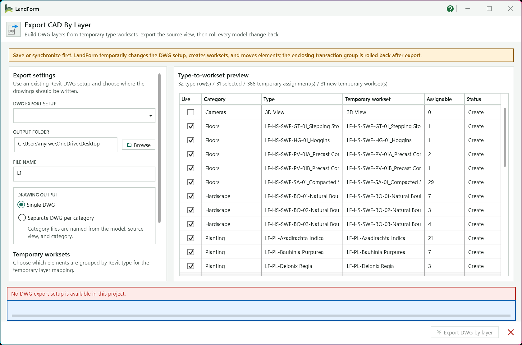
Reminder that the export changes the model temporarily and rolls every change back afterwards.
The Revit export setup whose layer names, colours and units are used.
Folder the DWG files are written to; type a path or press Browse.
Name of a single drawing; it defaults to the view name.
Single DWG puts every type on its own layer in one drawing; Separate DWG per category writes one drawing per category.
Scroll down to choose Active view elements or Whole model for visible categories, and the shape-point reset.
Counts the type rows, selected rows, temporary assignments and new worksets.
Untick a row to leave that type on its normal layer; rows with nothing assignable are unticked automatically.
Each category and type with the temporary workset, and so the DWG layer, it will get.
How many elements can be moved; Status says whether the workset will be created or already exists.
Follows each export stage with the progress bar; here it reports that the project has no DWG export setup.
Confirms the summary, exports the view and rolls every model change back. Disabled until a DWG export setup exists.
Open LandForm tab → Documentation panel → Export ▾ → CAD By Layer.
Choose the DWG setup. Pick the Revit export setup under DWG EXPORT SETUP; the active one is marked (active). Its layer names, colours and units are used, and the Workset modifier is added to it only inside the rollback-protected export.
Choose where the files go. Type or Browse to the OUTPUT FOLDER. For a single drawing, edit FILE NAME (it defaults to the view name).
Pick the drawing output. Single DWG writes one drawing with every selected type on its own layer. Separate DWG per category writes one drawing per Revit category, each named <Model> - <View> - <Category>, hiding the other categories in turn while it exports.
Decide which elements get temporary worksets. Active view elements groups only what is visible in the source view. Whole model for visible categories also includes elements elsewhere in the project whose categories occur in the view, which matters for a 3D view with a section box or a plan with a crop region. Changing this reloads the preview.
Tick Reset visible floor/toposolid shape points only when flattened slabs are required in the DWG; it temporarily resets the shape editing of every visible Floor and Toposolid before export and is slower on a large project.
Review the type-to-workset preview. Each row is one category and type with the temporary workset it will get, how many elements can be moved (Assignable) and whether that workset already exists (Existing) or will be created (Create). Untick Use on rows you want left on their normal layers; Select all and Clear work on every row, and Reload preview rebuilds the list after you change the model.
Rows with no assignable elements (for example elements you do not own) are unticked automatically.
Export. Press Export DWG by layer and read the confirmation, which repeats the view name, the number of type rows, temporary assignments and new worksets, and the files that will be written. Press Yes to run. The footer progress bar and the status band follow each stage: preparing the DWG layers, resetting shapes, creating worksets, assigning elements, exporting, and rolling back.
Press Cancel to stop after the current Revit operation; the rollback still happens.
Check the result dialog. It lists the DWG path (or the number of files and their folder), how many elements were assigned to how many temporary worksets, how many shapes were reset, and confirms that the temporary model changes were rolled back.
The output folder holds one DWG, or one per category, exported in shared coordinates and true colour with the layer naming of your chosen setup plus the Revit type name carried by the Workset modifier, so every type sits on its own layer. The Revit model is unchanged: the worksets, element assignments, shape resets, view visibility changes and DWG setup edits were made inside the "LF-Export CAD By Layer" transaction group and that group is rolled back, so there is nothing to undo and nothing to synchronise. The active view is refreshed afterwards and the preview reloads to show the restored state.
Pattern Overlay - <type>, so the hatch geometry lands on a layer of its own next to the host surface.Revit DWG export setup whose layers, colours and units are used. The Workset layer modifier is added to it only inside the rollback-protected export.
Folder the DWG file or files are written to. Created if it does not exist.
Opens a folder picker for the output folder.
File name for a Single DWG; defaults to the view name. Category exports are named from the model, view and category instead.
Writes one drawing containing every selected type on its own layer.
Writes one drawing per selected Revit category, hiding the other categories in the view while each is exported.
Groups only the model elements visible in the source view into temporary type worksets.
Also groups model elements throughout the project whose categories occur in the source view. Reloads the preview.
Temporarily resets the shape editing of every visible Floor and Toposolid before export so slabs export flat. Rolled back with everything else; slower on large projects.
Rebuilds the type-to-workset preview from the current model and scope without changing anything.
Ticks Use on every row that has assignable elements.
Removes the Use tick from every row.
One row per category and type: the temporary workset name, how many elements can be assigned, and whether that workset exists or will be created.
Confirms the summary, then prepares the DWG layers, creates the temporary worksets, assigns elements, exports the view and rolls every model change back.
Closes the window, or cancels a running export after the current Revit operation.

Documentation · Export · LandXML
LandXML is the hand-over format most civil and survey packages read, and the same small modeless toolbar runs both ways. Export takes the surfaces you select in Revit, triangulates their top faces exactly as Revit models them and writes one LandXML surface per element, so the engineer receives the geometry you graded rather than a re-interpolated copy; nothing in the model changes. Import reads a LandXML file, places its points through the project's shared coordinates and builds each surface as a Toposolid with the exact outline of the TIN, every TIN point as a shape point and the file's breaklines as split lines, so the surveyor's ground arrives on the survey grid as editable terrain.
LandForm tab→Documentation panel→Export ▾→LandXML
Button tooltip: “Export surfaces to LandXML 1.2, or import a LandXML surface as a Toposolid.”.xml file: the default is your Desktop, with a name made from the project title and the active view..xml file with a TIN surface (or a point group), Revit 2024 or newer, and at least one Toposolid type in the project.LandXML walkthrough. Until it is published, the steps and the annotated window below walk through the same workflow.
Open LandForm tab → Documentation panel → Export ▾ → LandXML.
Pick the direction. Click Export at the left of the bar (the bar reopens in the direction you used last). For the other direction, see Import workflow below.
Select the surfaces. Click Select, then window-select or click the floors, roofs, toposolids or topography to export and press Finish on the Revit options bar. The button changes to Select (N) and the status line reads "N surface(s) ready. Choose the XML file and export."
Press Esc during the pick to keep the previous set unchanged. Clicking Select again replaces the set rather than adding to it.
Decide how many surfaces the file should hold. Leave Combine (experimental) off to write one LandXML surface per Revit element, each named after the element and its unique ID. Turn it on only when the receiving software needs a single surface; the status line warns that overlapping sources may produce artifacts.
Decide how light the surface should be. Leave Simplify off to write Revit's own triangles exactly. Tick it for a lighter file: the outline stays as it is, interior points are kept only where the shape needs them, and the triangles are rebuilt as a clean Delaunay TIN instead of the long slivers a Revit top face often has. The box next to it is the tolerance in metres: no point that is left out sits further than that, up or down, from the lighter surface (5 m by default; a larger value gives a lighter file, a smaller one keeps more detail). Max edge (50 m by default) makes the triangles even: no triangle edge is longer than that, and no triangle has an angle under 20°, so long fans of slivers become a regular mesh. New points are placed at the surface's own elevation. Leave Max edge empty for no size limit; the triangles are then only kept free of slivers.
Choose the file. Accept the suggested path on your Desktop, type a new one, or press Browse and pick a folder and name. The extension must be .xml; LandForm adds it if you leave it off.
Export. Press Export LandXML. The status line counts the surfaces as they are converted ("Converted 2 of 3: ..."), reports "Writing LandXML 1.2 file..." and then turns green with the totals and the full path of the file. With Simplify on, it also says how many points the surfaces had before, for example "1,759 point(s) (simplified from 90,000 within 5 m)". While a large surface is simplified, the bar keeps moving and the status line names the stage ("choosing points", "evening out the triangles") with a running count and the time spent so far.
Hand the file over. Import the .xml into your civil-engineering or survey software as a surface. Because every surface is written in shared coordinates and metres, it should land on the survey grid without a further transformation.
After an export, a LandXML 1.2 file exists at the path shown in the status line. It holds one surface per selected element (or one combined surface), each defined as a TIN of points and triangles that reproduces Revit's own top-face triangulation, with northing, easting and elevation in metres in the project's shared coordinates: each point carries the same values Manage > Coordinates > Report Shared Coordinates shows for it, so an acquired coordinate system, a moved Survey Point and True North are all accounted for. The Revit model is untouched: there is no transaction, nothing to undo and no parameter is written. After an import, one Toposolid per chosen surface stands in the model on the chosen level, with the LandXML surface name (and the file name) in its Comments. Its boundary is the exact outline of the file's visible triangles, openings included where the TIN has holes; every TIN point is an editable shape point at its file elevation; and each breakline that went in is a split line. Plan duplicates within 0.1 mm were merged (Revit holds one elevation per plan position) and triangles the file marks invisible, which lie outside the surface boundary, were left out. The import is one undo step per surface ("LF-LandXML: Create Toposolid", then "LF-LandXML: Add Breaklines"). The toolbar stays open, so you can change the selection or the file and run again.
.xml, or paste its path into File. LandForm reads it at once and the status line describes it: how many surfaces, the unit the file names (metres, feet, US survey feet and the other LandXML units are all understood), the point, triangle and breakline counts. A file that is not LandXML, or holds no surface with three points, is reported in red..xml.Shows the export controls: write selected Revit surfaces to a LandXML 1.2 file.
Shows the import controls: read a LandXML surface and create it as a Toposolid.
Returns to Revit to window-select or click floors, footprint roofs, toposolids or topography; press Finish to accept. The label shows the current count, for example Select (3).
Experimental: write all selected geometry as one TIN. Overlapping source surfaces can produce artifacts; separate surfaces are the lossless option.
Shown in both directions. Export writes a lighter Delaunay TIN; Import builds the Toposolid from fewer points. The outline always stays; interior points are kept only where the shape needs them within the tolerance.
Largest height difference allowed between a dropped point and the lighter surface, in metres (above 0, up to 10; 5 by default). A value typed in millimetres, such as 50, is refused rather than read as 50 m. Enabled while Simplify is ticked.
Longest triangle edge, in metres, for even Delaunay triangles of about that size (50 by default; empty for no size limit). Triangles are always kept above 20° at their sharpest corner. Enabled while Simplify is ticked.
Full path of the .xml file to write. The folder must already exist; the .xml extension is added if you leave it off, and any other extension is rejected.
Opens a Save dialog filtered to LandXML (*.xml) files, starting in the folder currently shown.
Converts the selected surfaces to LandXML 1.2 in metres and shared coordinates and writes the file. Enabled once at least one surface is selected and a path is set.
Full path of the LandXML file to import. The file is read as soon as the path points at one, and the status line describes it.
Opens an Open dialog filtered to LandXML (*.xml) files.
Which surface of the file to build, or All surfaces. Every surface becomes its own Toposolid; point groups appear as Points: name.
Host level for the created Toposolid. Points keep their file elevations.
Toposolid type for the created surface.
Read the file as shared (survey) northing, easting and elevation and place it through the project's shared coordinates. Untick only for a file already in Revit's internal coordinates.
Replay the file's breaklines as split lines so kerbs and crests keep their edges. Slower on files with thousands of breakline segments.
Creates a Toposolid from each chosen LandXML surface. Enabled once a readable file, a level and a type are chosen.
Closes the toolbar.
Documentation · Export · GIS Export
GIS Export is the bridge from your Revit site model to the planning team's GIS. Each surface becomes one feature: either the exact 3D TIN that Revit models or, with Flat boundaries on, a filled 2D footprint polygon. Every feature carries the element's identity, type, level, materials, phases, workset and design option together with all of its instance and type parameters, and you can promote any parameter to its own attribute field for symbolising and querying. Coordinates are written in metres in the project's shared coordinate system and tagged with the EPSG code you confirm, so the layer lands in the right place without guesswork. The toolbar is modeless and read-only; the model is never changed.
LandForm tab→Documentation panel→Export ▾→GIS Export
Button tooltip: “Export selected surfaces with their Revit data to GIS.”EPSG:32640. If the project's site location already stores a coordinate system, LandForm shows it in the CRS box; otherwise you pick one from the catalogue. Never guess it from latitude and longitude.ogr2ogr.exe can be found on the PATH, in a standard install folder, or at the path in the LANDFORM_OGR2OGR environment variable. GeoJSON needs nothing extra.GIS Export walkthrough. Until it is published, the steps and the annotated window below walk through the same workflow.
Numbers on the screenshot match the legend. Hover a number or a legend row to highlight the other.

Window-select or click the floors, roofs, toposolids or topography to export and press Finish; the label shows the count.
Exports filled 2D footprint polygons from each element's sketch instead of the 3D TIN surface.
Chooses which parameters become their own attribute fields; available once surfaces are selected.
GeoJSON (.geojson) writes one file; File Geodatabase (.gdb) writes a folder and needs GDAL installed.
The coordinate reference system the export is tagged with; it cannot be typed into.
Opens the searchable catalogue of coordinate reference systems.
Full path of the file or .gdb folder to write; the extension follows the format.
Chooses the destination in a Save dialog.
Writes the attributed GeoJSON or File Geodatabase; enabled once surfaces, a path and a CRS are set.
Tells you what to do next and shows export progress; the surface count is at its right end.
Open LandForm tab → Documentation panel → Export ▾ → GIS Export.
Select the surfaces. Click Select, window-select or click the surfaces to export and press Finish on the Revit options bar. The button becomes Select (N) and the count appears at the right of the status line.
Press Esc during the pick to keep the previous selection. Clicking Select again replaces the set.
Choose the geometry. Leave Flat boundaries off for the exact 3D TIN surface, written as one polygon per triangle with elevations. Turn it on for filled 2D footprint polygons taken from each element's sketch, holes included; the attributes are the same either way.
Choose the attribute fields. Press Parameters (default). The dialog lists every instance and type parameter found on the selected surfaces and their types. Tick the ones your GIS workflow filters or labels on, or type in the filter box and press Select visible to tick a whole group, then press Add parameters. The button now reads Parameters (N).
Until you configure it, the default set is Area, Type Name and, for 3D export, Volume. The complete parameter sets are always written as well, as nested instance_parameters and type_parameters objects.
Pick the format. Choose GeoJSON (.geojson) or File Geodatabase (.gdb) under Format. The extension of the path in File switches to match.
Confirm the coordinate reference system. If CRS is empty, or shows something other than the system your shared coordinates use, press Select beside it. Filter the catalogue by name or EPSG code, then double-click the row or press Select. Recently used systems are listed first.
The CRS box cannot be typed into; the selector is the only way to set it, and Export GIS stays disabled until it holds a value.
Set the destination. Accept the Desktop path named after the project and the active view, type a new one, or press Browse. GeoJSON is a single file; a File Geodatabase is a .gdb folder.
Export. Press Export GIS. The status line shows each surface being read and converted with a percentage, then "Writing attributed GeoJSON GIS file..." or "Creating the Esri File Geodatabase with GDAL...", and finally turns green with a summary such as "Exported 3 3D TIN feature(s) with 1240 triangle(s) to ..." followed by the path.
A GeoJSON FeatureCollection, or a .gdb folder containing a LandForm_Surfaces layer, exists at the chosen path and is tagged with the CRS you confirmed. Each selected surface is one MultiPolygon feature: triangles with east, north and elevation in metres for the 3D TIN, or flat footprint rings for boundaries. Its properties carry the Revit element ID and unique ID, name, category, family and type, level, workset, design option, phases created and demolished, pinned state, triangle and vertex counts, a material list with areas and volumes, the complete instance and type parameter sets, and one param_... or type_param_... field per parameter you promoted. A landform_metadata block records the source model and path, Revit version, coordinate order (east, north, elevation), unit and site location. Nothing in the Revit model changes.
projinfo when it is installed; otherwise a built-in list of WGS 84 UTM zones and Pseudo-Mercator is offered, plus whatever the project stores. Up to eight recently used systems are remembered between sessions.param_ for instance parameters and type_param_ for type parameters and cut to 60 characters; a clash gets a _2 suffix. In a File Geodatabase the nested parameter objects and the material list are written as text, because that format has no nested fields.ogr2ogr.exe cannot be found the export stops with a red message explaining how to install GDAL or set LANDFORM_OGR2OGR; the conversion itself is limited to two minutes.Returns to Revit to window-select or click floors, footprint roofs, toposolids or topography; press Finish to accept. The label shows the current count, for example Select (3).
Export attributed, filled 2D footprint polygons taken from each element's sketch instead of the 3D TIN surface. Legacy topography has no sketch and cannot be exported this way.
Opens the parameter dialog listing the instance and type parameters of the selected surfaces, so you can promote them to individual GIS attribute fields. The label shows (default) or the number chosen.
GeoJSON (.geojson) writes a single file; File Geodatabase (.gdb) writes a folder through GDAL's ogr2ogr and needs GDAL 3.6 or newer installed. Switching also swaps the extension in File Path.
The projected coordinate reference system the export is tagged with, for example EPSG:32640. Read-only: it is filled from the project's stored site coordinate system or from the selector, never guessed from latitude and longitude.
Opens the searchable coordinate reference system catalogue; the chosen authority ID is written into Coordinate Reference.
Full path of the .geojson file or .gdb folder to write. The parent folder must exist and the extension must match the chosen format (it is added if left off).
Opens a Save dialog filtered to the chosen format, starting in the folder currently shown.
Reads the selected surfaces, converts them to shared coordinates in metres and writes the attributed GeoJSON or File Geodatabase. Enabled once surfaces, a path and a CRS are all set.
Closes the toolbar.
Search parameter name or scope.
Ticks every parameter currently shown by the filter, so you can add a whole group at once.
Unticks every parameter in the list, including rows hidden by the filter.
One row per instance or type parameter found on the selected surfaces and their types. Tick Add to export it as its own attribute field; Scope shows whether it is an Instance or Type parameter.
Closes the dialog and keeps the previous parameter selection.
Saves the ticked parameters as the attribute fields to add; the toolbar button then shows their count.
Search by CRS name, EPSG code, or authority.
Projected coordinate reference systems with their authority ID, for example EPSG:32640; recently used systems are listed first. Double-click a row to choose it.
Closes the selector and keeps the previous CRS.
Uses the highlighted CRS for the export and adds it to the recently used list.

Documentation · Export · Cloud Export
Cloud Model Export browses the Forma, ACC and BIM 360 hubs available to the Autodesk account you are signed in to in Revit, so no separate login is needed. You queue the models you want, from the cloud tree or from .rvt files on disk, tick the output formats, and LandForm opens each model in the background, exports it, checks that every file was really written and closes it again. Exporter pop-ups and warnings that would normally stall an unattended run are dismissed and recorded, and a model that fails is reported while the rest of the batch carries on.
LandForm tab→Documentation panel→Export ▾→Cloud Export
Button tooltip: “Batch export cloud and local Revit models to NWC, DWFx, or a local central.”.rvt files can be queued without signing in.Cloud Export walkthrough. Until it is published, the steps and the annotated window below walk through the same workflow.
Numbers on the screenshot match the legend. Hover a number or a legend row to highlight the other.
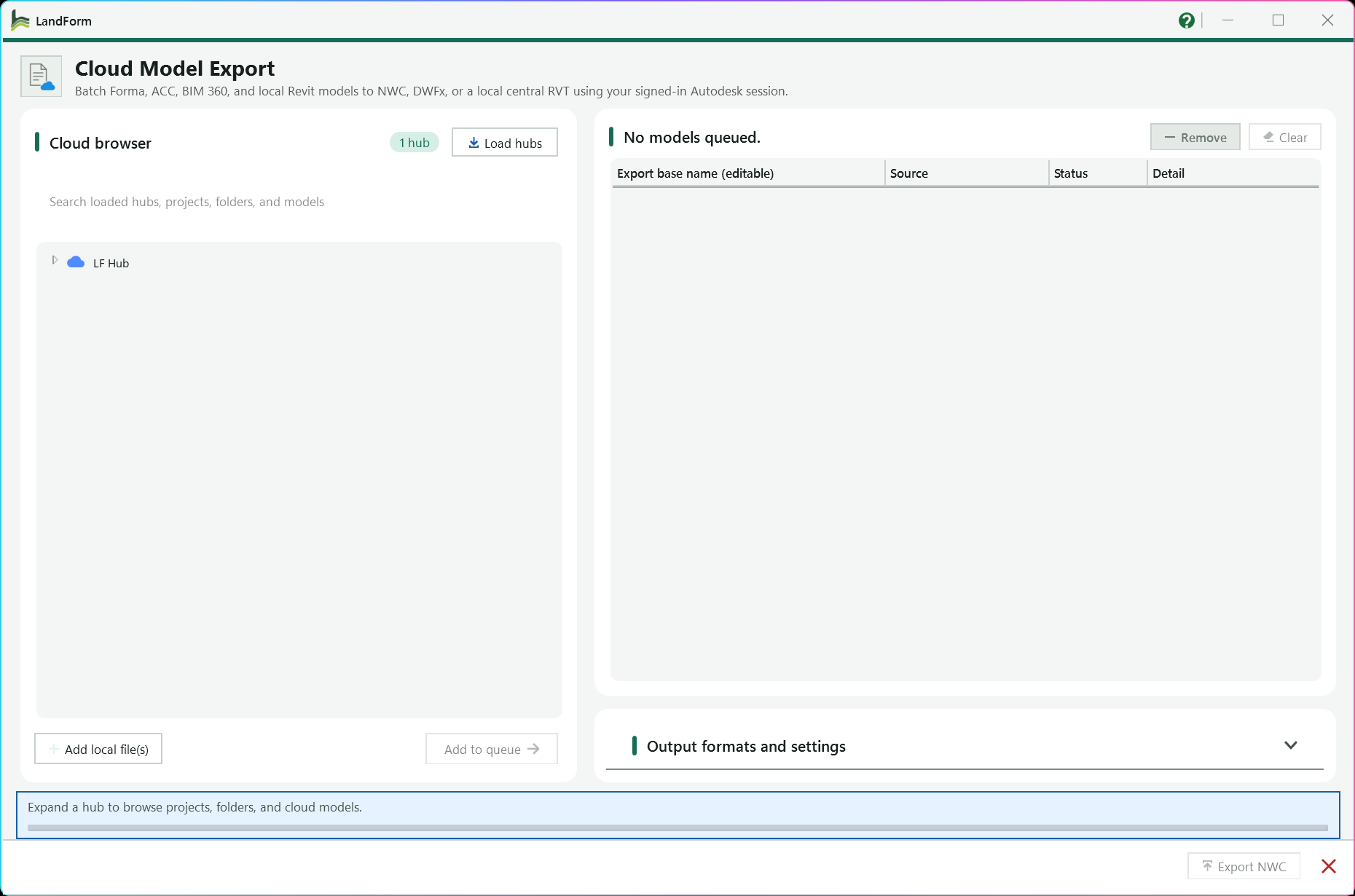
Reads the hubs of your signed-in Autodesk account; the badge beside it shows how many were found.
Tells you what to do next and shows progress while the batch runs.
Expand hubs, projects and folders and tick the models you want; each branch loads the first time you open it.
Filters the names already loaded; it never loads new branches.
Queues the ticked models, or the highlighted model or folder when nothing is ticked.
Queues .rvt files from disk with the source Local file.
The queue: rename each output here, and follow Status and Detail during the run.
Removes the highlighted row, or empties the queue.
Expand to tick NWC, DWFx and/or Save as Model, set their options and choose the destination folder.
Runs the batch; the label follows the formats you ticked.
Closes the window; during a batch it becomes Cancel and stops after the current model.
Open LandForm tab → Documentation panel → Export ▾ → Cloud Export.
Load your hubs. Press Load hubs. The badge next to Cloud browser changes from Not loaded to the number of hubs found and the status line asks you to expand one. Expand hubs, projects and folders; each branch is read the first time you open it and shows Loading... meanwhile.
Type in the search box to filter the names already loaded. Searching never loads new branches, so expand the project first.
Queue cloud models. Tick the models you want, in any folders, and press Add to queue. With nothing ticked, the button adds the highlighted model, or every model inside the highlighted folder. The ticks are cleared afterwards and a model already in the queue is refused.
Queue local files (optional). Press Add local file(s) and choose one or more .rvt files. They join the queue with the source Local file.
Tidy the queue. The card title counts the queued models. Edit the Export base name (editable) cell to rename the output; the extension is added per format, and a blank name falls back to the model's title. Highlight a row and press Remove, or press Clear to empty the queue.
Tick the formats. Expand Output formats and settings and tick NWC, DWFx and/or Save as Model in the tab headers. Every ticked format writes its own file and they run in the order NWC, DWFx, then Save as Model.
Set each format's options. On NWC, tick the Navisworks options you need and choose Entire project (full model) or One 3D view whose name contains the text you type. On DWFx, choose Temporary full-model 3D view or a named view and whether to Export object data (properties) and Export textures. On Save as Model, decide whether to Overwrite existing files.
Choose the destination folder in the text box or with Browse....
Run the batch. Press the main button. Its label follows your ticks: Export NWC, Export DWFx, Save as Model, or Export selected outputs when more than one format is ticked. The Status column moves through Queued, Exporting and Done, Skipped or Failed, with the reason in Detail, while the footer shows progress. The close button becomes Cancel and stops the batch after the current model.
Read the report. When the batch ends a dialog summarises how many models succeeded, how many files were written, skipped or failed, the destination folder, any notes and the path of the diagnostic log. Models that did not finish stay in the queue as Queued; press the export button again to retry only those.
The destination folder holds one .nwc, .dwfx and/or .rvt file per queued model, each named from its editable base name and verified to be non-empty before it counts as written. A saved RVT is a new detached local central with worksets preserved, and the _backup folder Revit creates beside it is removed. Your open project is never re-pathed or edited; when the window closes Revit simply refreshes the active view. Successful rows leave the queue, failed or skipped rows remain for a retry, and everything that happened, including any exporter dialogs that were dismissed, is written to LandForm-CloudExport-diag.txt in your temp folder.
| NWC option | What it does |
|---|---|
| Convert element properties | Writes the Revit element properties into the NWC. |
| Export links | Includes linked Revit models. |
| Room as attribute | Attaches room information to elements as an attribute. |
| Find missing materials | Looks up materials that are not assigned directly. |
| Divide into levels | Groups the exported elements by level. |
| Export parts | Exports Parts instead of their parent elements; views set to Show Original always export the originals. |
| Room geometry | Exports rooms as geometry. |
| All parameters / Element parameters | Choose which parameter set goes into the file; untick both for none. |
| Export element IDs | Writes the Revit element ID with each item. |
| Internal coordinates | Uses Revit internal coordinates; unticked exports shared coordinates. |
| Export URLs | Includes URL parameters. |
| Linked CAD (Revit 2020+) | Converts linked CAD formats. |
| Convert lights (Revit 2020+) | Converts Revit lights. |
| Faceting factor (Revit 2020+) | Tessellation factor for curved surfaces, accepted between 0 and 1 (default 1). |
No separate LandForm window. This command runs directly from Revit selection and prompts; follow the workflow above and the messages shown beside the cursor or on Revit's status bar.

Documentation · Sheets · By Scope Box
Setting up site plan sheets by hand means creating a plan per level, duplicating it per scope box, applying each scope box, making a sheet, placing the viewport in the same spot every time and numbering it all consistently. By Scope Box does that for one or more drawing sets at once. Each set is a plan view type with its own start number; each ticked level gets a parent plan, an optional overall sheet and one dependent view and sheet per ticked scope box; and every viewport lands at the same sheet coordinates. Naming patterns, numbering, viewport type, a sheet parameter and a generic annotation stamp are set once under Settings and remembered for next time.
LandForm tab→Documentation panel→Sheets ▾→By Scope Box
Button tooltip: “Create sheets and plan views by scope box.”L-, how many digits to pad to, a start number per drawing set and the step between levels (default 100), chosen so nothing collides with sheets that already exist.By Scope Box walkthrough. Until it is published, the steps and the annotated window below walk through the same workflow.
Numbers on the screenshot match the legend. Hover a number or a legend row to highlight the other.
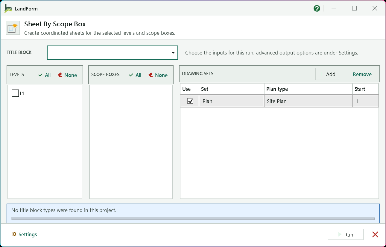
The title block type, listed as family: type, used on every sheet in this run.
Tick the levels to document, lowest first; All and None tick or clear the whole list.
Tick each scope box that should get its own dependent view and sheet on every ticked level.
One row per drawing set: include it, name it, choose its plan view type and its first sheet number.
Add another drawing set, or delete the highlighted row.
Unfolds the Views, Naming and Output settings for scales, name patterns and numbering.
Checks the inputs, then creates every view and sheet in one step.
Reports missing inputs, such as no title block types, and names each sheet as it is created.
Open LandForm tab → Documentation panel → Sheets ▾ → By Scope Box.
Pick the title block. Choose a type from TITLE BLOCK, listed as family: type. Every sheet in this run uses it.
Tick the levels. In LEVELS, tick the levels to document, or press All or None. Levels are listed from lowest to highest.
Tick the scope boxes. In SCOPE BOXES, tick each box that should get its own dependent view and sheet on every ticked level.
If you only want overall sheets, leave the list unticked and turn off Create scope-box sheets under Settings.
Define the drawing sets. Each row in DRAWING SETS is one plan series: tick Use, type a Set name (it appears in view and sheet names; the first row is called Plan), choose the Plan type and enter the Start sheet number. Press Add for another series, for example a planting set on a different plan type with its own number range, and Remove to delete the highlighted row.
Review the settings (optional). Press Settings to unfold the sheet settings; the same button then reads Hide.
Views: tick Create overall sheet (one per level at the overall Scale, default 500 for 1:500) and Create scope-box sheets (at the scope-box Scale, default 200), decide whether to Set annotation crop offsets to zero and Hide annotation categories in scope views, and set the VIEWPORT CENTER (MM) X and Y where every viewport is placed. Naming: edit the patterns for the overall, scope-box and parent view names and for the sheet name using {SetName}, {Level}, {ScopeBox} and {ViewName}. The Example line under each box updates as you type. Output: set Number prefix, Minimum digits (zero padding, default 3) and Level step (default 100), pick a Viewport type or keep Project default, optionally name a Sheet parameter and the Parameter value to write on every new sheet, and tick Place generic annotation with a symbol and its X and Y in millimetres to stamp each sheet. Save settings stores all of this without running; running stores it too.
Run. Press Run. LandForm first checks the inputs, including that no planned sheet number repeats or already exists in the project, and stops with a precise message if something is missing. The status line then names each sheet as it is created, for example "Created 101 - Plan - L1 OVERALL", while the progress bar fills.
Confirm. A dialog reports "Scope-box sheets created" with the number of sheets and views, and the window closes.
For every ticked drawing set and level the project now holds a parent plan view, named by the parent pattern and set to the scope-box scale, plus an overall plan view and sheet when enabled, plus one dependent plan view with its scope box applied and one sheet for each ticked scope box. Every sheet carries the chosen title block, a name from the sheet pattern, a number built from the prefix, start, level step and digit count, its viewport centred at the X and Y you set and switched to the chosen viewport type, the optional sheet parameter value and the optional generic annotation. The whole series is created in one transaction named "LF-Sheet By Scope Box: Create Sheets", so a single Undo removes it all.
Title block type placed on every sheet created in this run, listed as family: type.
Ticks every level (or every scope box, for the button above that list).
Unticks every level (or every scope box).
Project levels from lowest to highest; tick the ones that should receive views and sheets.
The tick in front of each level or scope box that includes it in the run.
Scope boxes in the project; each ticked box gets a dependent view and sheet on every ticked level.
Adds another drawing set row with the first plan type and start number 1.
Deletes the highlighted drawing set row.
One row per plan series: Use includes it, Set names it, Plan type is the view type it creates and Start is its first sheet number.
Floor-plan or structural-plan view type used for every view of that drawing set.
Stores the Views, Naming and Output settings and the drawing sets for next time without creating anything.
Which sheet kinds to create, their scales, crop handling and the viewport position.
Creates one overall plan view and sheet per level and drawing set.
Scale denominator for the overall views; 500 means 1:500.
Creates one dependent view and sheet per ticked scope box, per level and drawing set.
Scale denominator for the parent and scope-box views; 200 means 1:200.
Pulls each scope-box view's annotation crop tight to the scope box so the viewports line up exactly.
Switches off every annotation category in the scope-box views.
Horizontal position of each viewport centre in millimetres from the sheet origin.
Vertical position of each viewport centre in millimetres from the sheet origin.
Name patterns for the views and sheets, with live examples.
Pattern for the overall view name; placeholders {SetName} and {Level}.
Pattern for each scope-box view name; placeholders {SetName}, {Level} and {ScopeBox}.
Pattern for the parent plan that hosts the dependent views; placeholders {SetName} and {Level}.
Pattern for the sheet name; {ViewName} copies the generated view name and the other placeholders also work.
Numbering, viewport type, sheet parameter and annotation stamp settings.
Text placed in front of every sheet number, for example L-.
Zero-pads the numeric part to at least this many digits; 3 turns 1 into 001.
Added to the start number for each further level, so every level gets its own number range.
Viewport type applied to every placed viewport, or Project default to leave Revit's default.
Optional name of an existing editable sheet parameter to fill on every new sheet.
Value written to that parameter; text, whole numbers and numbers are accepted.
Places a generic annotation symbol on every sheet, for example a stamp.
Generic annotation type to place, or None.
Horizontal position of the annotation in millimetres from the sheet origin.
Vertical position of the annotation in millimetres from the sheet origin.
Shows or hides the sheet settings tabs; the label switches between Settings and Hide.
Validates the inputs and creates all views and sheets in one transaction, then closes the window.
Closes the window without creating anything.

Documentation · Sheets · Align Viewports
A drawing set reads far better when every plan sits in the same spot on its sheet, but nudging viewports by eye across dozens of sheets is slow and never quite exact. Align Viewports lists every viewport in the project, lets you tick the ones to fix, and then asks you to pick one viewport on the open sheet that is already where it should be. Each ticked viewport is moved on its own sheet so its centre or corner lands at the same sheet position as that template.
LandForm tab→Documentation panel→Sheets ▾→Align Viewports
Button tooltip: “Align viewports across sheets.”Align Viewports walkthrough. Until it is published, the steps and the annotated window below walk through the same workflow.
Numbers on the screenshot match the legend. Hover a number or a legend row to highlight the other.
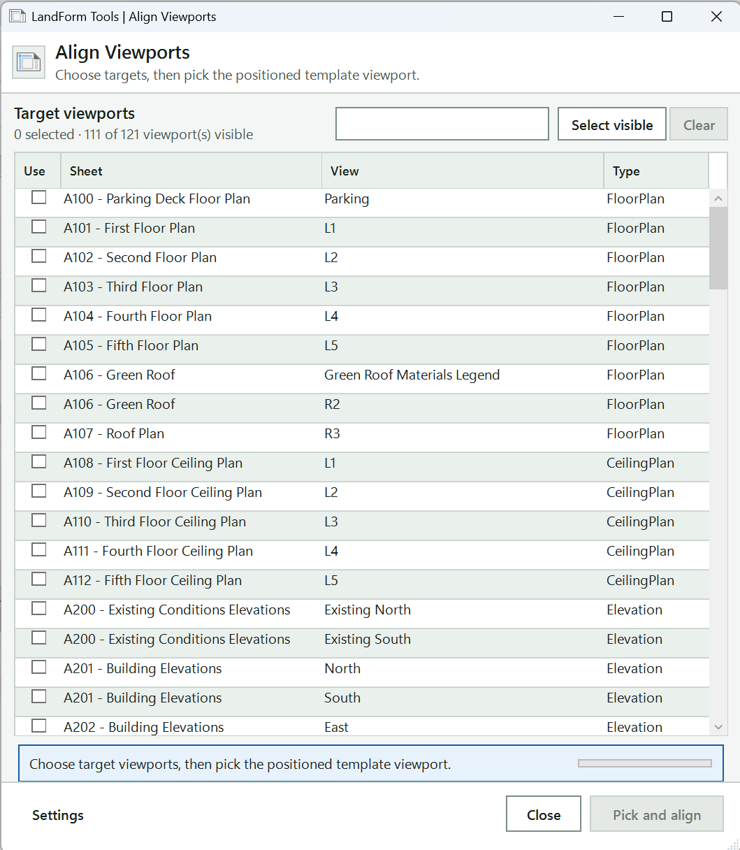
Filters the list by sheet number, sheet name, view name or view type.
Shows how many viewports are selected and how many the search leaves visible.
Every viewport in the project; tick Use on each one to move.
Select visible ticks every row the search shows; Clear unticks them all.
Shows the Alignment anchor and the Exclude legends and Exclude schedules options.
Tells you the next step: choose the targets, then pick the template viewport.
Hides the window so you can click the template viewport on the active sheet, then aligns the ticked targets.
Open LandForm tab → Documentation panel → Sheets ▾ → Align Viewports.
Open the template sheet. Make the sheet with the correctly placed viewport the active view, then start Align Viewports. The window lists every viewport in the project by sheet, view and view type.
Find the targets. Type in the search box to filter by sheet number, sheet name, view name or view type, for example a level name or FloorPlan. The line under Target viewports shows how many are selected and how many are visible.
Tick the targets. Tick Use on each viewport to move, or press Select visible to tick every row the search shows. Clear unticks them all.
Choose the anchor (optional). Press Settings to show the alignment options. Pick the Alignment anchor: Center, Top left, Top right, Bottom left or Bottom right. Leave Exclude legends and Exclude schedules on to keep those out of the list.
Pick the template and align. Press Run. The window hides and Revit asks you to select the template viewport on the active sheet; click it. Every ticked viewport moves so its anchor matches the template's anchor position on the sheet.
Press Esc instead of picking to cancel; the window comes back with your ticks kept.
Every ticked viewport now sits at the same position on its own sheet as the template viewport, measured at the anchor you chose. Only viewport positions change; views, crops and sheets are untouched. The move is one undo step named "LF-Align Viewports", and a message confirms how many viewports were aligned.
The point matched between the template and each target: Center, Top left, Top right, Bottom left or Bottom right.
Hides legend viewports from the list and unticks any that were selected.
Hides schedule viewports from the list and unticks any that were selected.
Search sheet number, sheet name, view name, or view type.
Ticks every viewport the current search shows.
Unticks every target viewport.
Every viewport in the project with its sheet, view and view type; tick Use on the ones to move.
Shows or hides the alignment anchor and exclude options.
Pick the positioned template viewport, then align the checked targets.
Closes Align Viewports without moving anything.
LandForm ribbon panel
Rename, parameters, surface types, worksets, clean-up and pinning.
Management · Rename
Rename is the tool for bringing a project's names into line with a standard: adding an LF_ prefix to every planting type, fixing a typo repeated across forty types, or swapping a client code for a new one. You choose where the names come from (the whole project, the active view or your current selection), build proposed names with prefix, suffix, removal and find/replace rules, check the result row by row, and apply the checked rows in one step. The same grid doubles as a family exporter: switch to Export families and each checked loadable family is saved as its own editable .rfa file.
LandForm tab→Management panel→Rename
Button tooltip: “Batch rename project families and types.”LandForm Family Export folder in your Documents.Rename walkthrough. Until it is published, the steps and the annotated window below walk through the same workflow.
Numbers on the screenshot match the legend. Hover a number or a legend row to highlight the other.
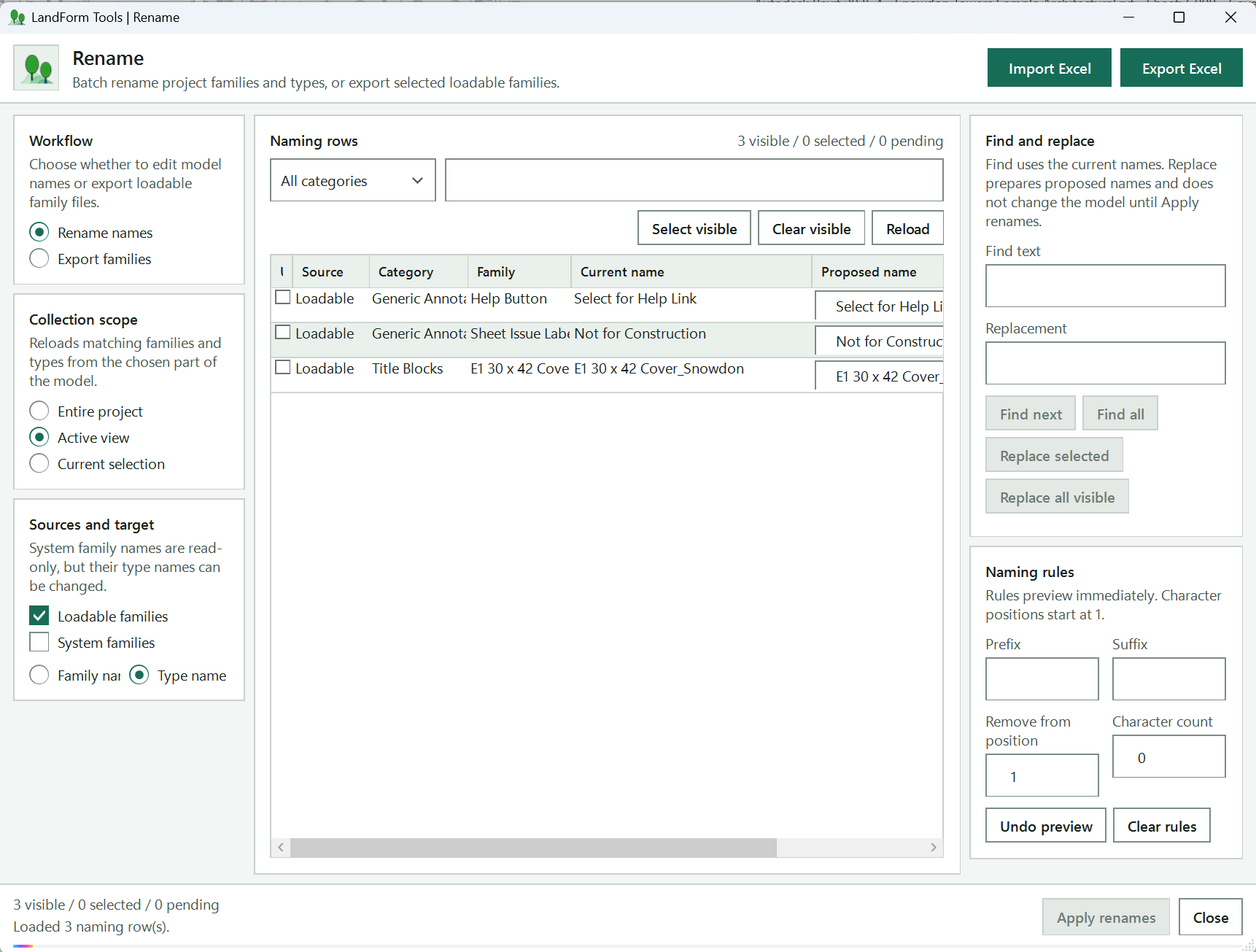
Rename names changes names in the model; Export families saves checked loadable families as RFA files.
Entire project, Active view or Current selection; the grid reloads immediately.
Shows how many rows were loaded, the run totals and the export progress; here it reports that nothing matched the scope.
Tick Loadable families, System families or both, then pick Family name or Type name below.
Show only one Revit category, or search names and status to narrow the rows.
Ticks or unticks Use on every row shown, or reads the names from Revit again.
One row per family or type with its current and Proposed name; tick Use on the rows to apply. You can type straight into a proposed name.
Prefix, Suffix, Remove from position and Character count; the proposed names preview as you type.
Matches Find text in the current names, then Replace selected or Replace all visible prepares proposed names without changing the model.
Saves the visible rows to a workbook for bulk edits, then loads the ProposedName column back.
How many rows are visible, selected and pending.
Renames the checked pending rows in one undoable step; reads Export families in export mode.
Saves the settings and closes Rename.
Open LandForm tab → Management panel → Rename.
Choose the job. Under Workflow, keep Rename names to change names in the model, or pick Export families to save checked loadable families as RFA files.
Set the scope. Pick Entire project, Active view or Current selection. The grid reloads immediately and the status line tells you how many naming rows were loaded.
Choose what to rename. Tick Loadable families, System families or both, then pick Family name or Type name. Family name lists one row per family; type name lists one row per type.
System family names are read-only, so ticking System families keeps the target on Type name.
Narrow the list. Use the category drop-down and the search box to show just the rows you care about, then press Select visible to tick Use on all of them. Clear visible unticks them again.
Build the proposed names. Type a Prefix or Suffix, or set Remove from position and Character count to strip characters; the Proposed name column previews every change at once.
To swap text, enter Find text and Replacement, use Find next or Find all to see which current names match, then press Replace selected for the highlighted rows or Replace all visible for every visible match. You can also type straight into a Proposed name cell. For bulk edits outside Revit, press Export Excel, change the ProposedName column in the workbook, then press Import Excel to load the names back by RenameElementId.
Check the pending rows. Rows whose proposed name differs from the current name show Pending. Make sure Use is ticked on each one you want to apply; the counter above the grid shows how many are selected and pending.
Apply. Press Apply renames. LandForm renames the checked rows in one undoable step named "LF-Rename Families and Types" and sets each row's Status to Renamed, Skipped or Failed.
In export mode, set the Output folder (or Browse folder), choose whether to Group files by Revit category, Overwrite existing family files and Delete numbered Revit backup files, then press Export families.
In rename mode the checked families or types now carry their proposed names, the grid shows Renamed on each row, and the status line totals the renamed, skipped and failed rows. One Undo in Revit reverts the whole batch. In export mode nothing in the model changes; instead the output folder holds one .rfa per checked loadable family (in category subfolders when grouping is on), the status line shows the counts and the folder path, and families that Revit cannot edit are reported as skipped. Your scope, sources, filters, removal rule and export options are saved for the next session.
Name 2.rfa rather than replaced.Reads the first worksheet of a workbook and copies its ProposedName values onto the rows whose RenameElementId matches; other rows are left unchanged.
Saves the visible rows (ID, source, target, category, family, type, current name, proposed name, status) to an .xlsx workbook you can edit and import again.
Rename mode: proposed names are written to the model when you press Apply renames.
Export mode: checked loadable families are saved as .rfa files instead of being renamed. Sources switch to loadable families and the grid lists one row per family.
Collects every loadable family type and model system type in the project.
Collects only the types used by elements visible in the active view.
Collects only the types of the elements that were selected in Revit when you opened the tool.
Includes types of families loaded from .rfa files. At least one source always stays ticked.
Includes model system types such as Floor, Wall and Toposolid types. Their family names are read-only, so ticking this keeps the target on Type name.
Lists one row per family and renames the family itself. Loadable families only.
Lists one row per type and renames the type.
Show only rows from one Revit category.
Search category, family, type, current name, proposed name, and status.
Ticks Use on every row currently shown by the filters.
Unticks Use on every row currently shown by the filters.
Read matching names from the current Revit document again.
Check Use on the rows to include in the next rename or family export. Status reads Ready, Pending, Read-only, Renamed, Exported, Skipped or Failed.
Edit the proposed name directly or use the naming rules. Read-only on system family name rows.
Text to look for in the current names, ignoring case. The find and replace buttons stay disabled while it is empty.
Text written in place of every match of Find when you prepare a replacement. Leave it empty to delete the matched text.
Highlights the next visible row whose current name contains the Find text and reports "Found n of m"; wraps round to the first match.
Filters the grid to the rows whose current name contains the Find text. Change the category or clear Find to show every row again.
Prepares proposed names for the highlighted rows (or the focused row) by applying the removal, find/replace, prefix and suffix rules. The model is not changed.
Prepares proposed names for every visible row whose current name contains the Find text.
Text added at the start of every proposed name; the preview updates as you type.
Text added at the end of every proposed name; the preview updates as you type.
Position of the first character to strip from each current name, counting from 1.
Number of characters to strip from that position. 0 removes nothing.
Resets every proposed name to the current model name and clears the Pending state.
Empties Find, Replacement, Prefix and Suffix, resets the removal to position 1 and count 0, and rebuilds the preview.
Folder where exported Revit family files will be saved. Defaults to a LandForm Family Export folder in Documents.
Opens a folder picker for the export folder.
Saves each exported family in a subfolder named after its Revit category.
Replaces an existing .rfa of the same name. When off, a numbered copy such as "Name 2.rfa" is written instead.
After the export, deletes Revit backup copies (files ending .0001.rfa and similar) found in the output folder.
Reads Apply renames in rename mode and Export families in export mode. Enabled once a checked row has a pending change, or a checked loadable family is available to export.
Saves the settings and closes Rename.

Management · Parameter Manager
Parameter Manager replaces the long round trip through Revit's Project Parameters dialog when you need to set up a batch of parameters at once. The window loads every parameter already bound in the project, lets you add new rows by name (ten at a time if you like), assign categories to several rows in one go, and only writes to the model when you press Run. Everything you stage can be imported from, or exported to, an Excel workbook or a Revit shared parameter file.
LandForm tab→Management panel→Parameter Manager
Button tooltip: “Create, review, exchange, bind, and remove project parameters.”LF_SharedParameters.txt in the LandForm Tools data folder, under the group LF Parameters. Point Definition file at your office file if you prefer.Parameter Manager walkthrough. Until it is published, the steps and the annotated window below walk through the same workflow.
Numbers on the screenshot match the legend. Hover a number or a legend row to highlight the other.
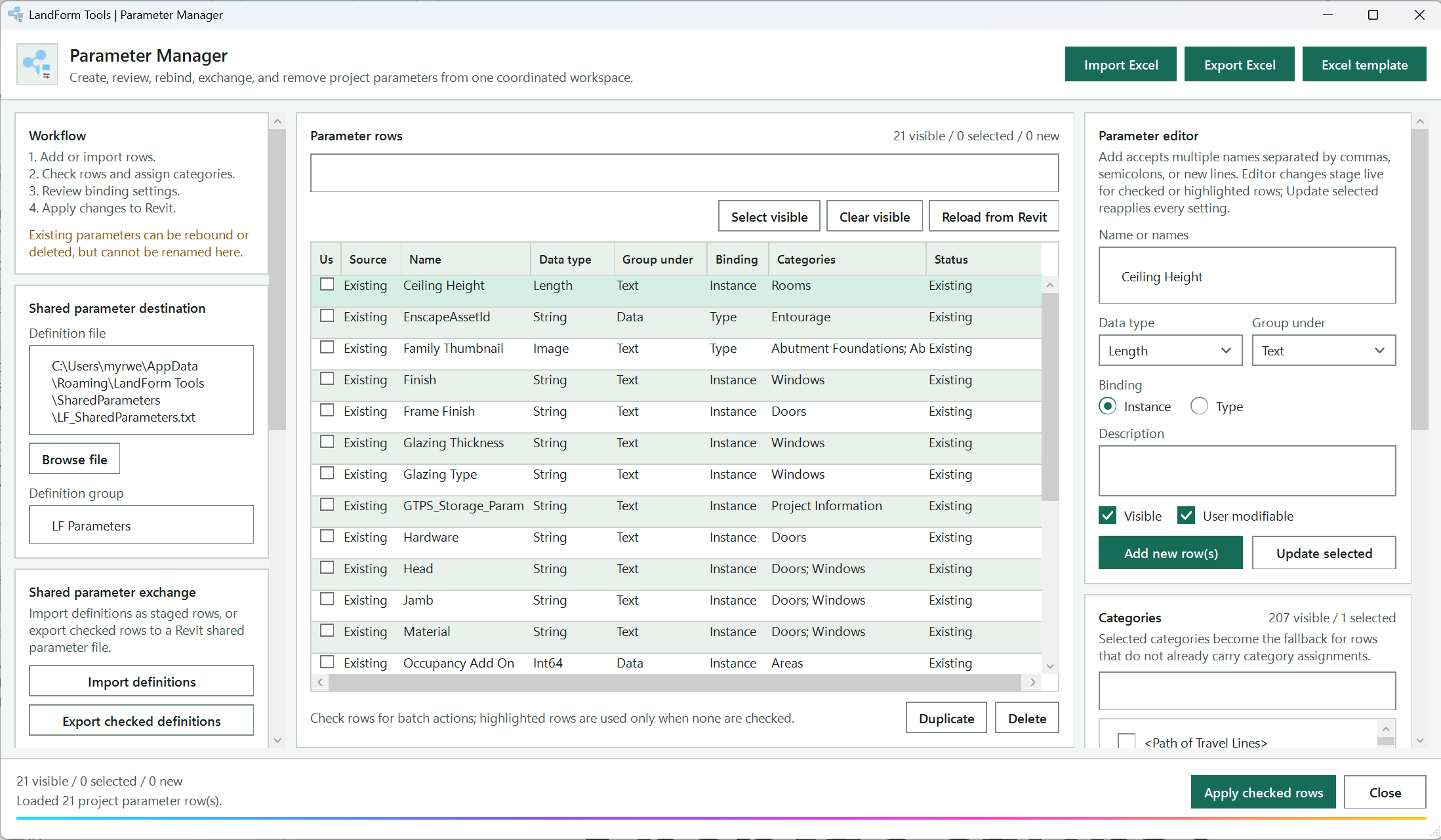
Definition file, Browse file and Definition group set the shared parameter file and group that receive new definitions.
Every bound project parameter with its source, name, data type, group, binding, categories and status; check rows to include them in batch actions.
Filters the grid, checks or unchecks every row shown, or discards staged rows and reads the project again.
Untick it to see only the rows you have staged.
Type one or more new parameter names, separated by commas, semicolons or new lines.
Sets the parameter's data type, its Properties palette group, and whether it is an Instance or Type parameter.
The description and flags stored in the shared parameter definition.
Adds one checked New row per name, or reapplies every editor setting, categories included, to the checked or highlighted rows.
Stages rows from a workbook, exports the visible rows, or creates an import-ready workbook.
Import definitions stages rows from a shared parameter .txt file; Export checked definitions writes the checked rows to one.
Filter and tick the categories to bind; ticking one while rows are checked or highlighted stages it on those rows.
Copies the target rows as new staged rows, or removes them; deleting an existing parameter is permanent after you confirm.
Creates and binds the checked rows in Revit after a confirmation.
Shows how many rows are visible, checked and new, and what the last action did.
Open LandForm tab → Management panel → Parameter Manager.
Review what is already there. The grid lists every bound project parameter with its Source, Name, Data type, Group under, Binding, Categories and Status. Type in the search box to filter by any of those; untick Show existing project parameters to see only the rows you have staged.
Add new rows. In Parameter editor, type one or more names in Name or names (separate them with commas, semicolons or new lines), choose the Data type (Text, Multiline Text, Integer, Number, Length, Area, Volume, Angle, Yes/No or URL) and Group under, pick Instance or Type, add a Description, set Visible and User modifiable, then press Add new row(s). Each name becomes a checked row with the status New.
You can also stage rows with Import Excel (a workbook made with Excel template) or Import definitions (a Revit shared parameter .txt file).
Assign categories. Filter the Categories list, tick the categories you need, and press Assign to rows to write them to the checked rows (or the highlighted rows when nothing is checked). Ticking a category while rows are checked or highlighted also stages it straight away. Categories left ticked when you press Run act as the fallback for rows that still have none.
Rebind an existing parameter. Click an existing row to load it into the editor, change Binding, Group under or the categories, and the row's status changes to Binding pending. Press Update selected to reapply every editor setting, categories included, to all checked or highlighted rows. Existing parameters cannot be renamed here.
Duplicate or remove rows. Duplicate copies the target rows as new staged rows named "Name Copy". Delete removes staged rows outright; for existing parameters it asks you to confirm and then permanently deletes them from the project.
Run. Check the rows to apply and press Run. After a confirmation, LandForm creates the new shared parameters in the definition file and group, binds them to their categories, and re-inserts the bindings of existing rows. The Status column reports Created, Binding updated, Skipped: no categories or Failed per row and a summary dialog follows.
Export when you need a record. Export Excel writes the visible rows to a workbook, Export checked definitions writes the checked rows to a shared parameter .txt file, and Excel template creates an import-ready workbook with instructions and a sample row.
The project now carries the checked parameters as shared project parameters, bound to the categories you chose, with the binding kind, group, description and visibility you set. New definitions are also appended to the shared parameter file so other projects can reuse the same GUIDs. The whole apply is one undo step named "LF-Parameter Manager: Apply Parameters"; deletions are a separate step named "LF-Parameter Manager: Delete Parameters". The summary line under the grid shows how many rows are visible, checked and new.
Stage parameter rows from a Parameter Manager Excel workbook.
Export all visible parameter rows to Excel.
Create an import-ready workbook with instructions and a sample row.
Shared parameter file used when new project parameters are created.
Picks the shared parameter .txt file that new definitions are written to.
Group inside the shared parameter file that receives new definitions (LF Parameters by default); also written into exported definition files.
Reads the PARAM lines of a Revit shared parameter .txt file and stages each one as a new, checked Instance row.
Writes the checked rows to a new Revit shared parameter .txt file, keeping each row's GUID where it has one.
Shows or hides the rows that already exist in the project, so you can work on staged rows alone.
Search name, data type, property group, binding, category, or status.
Checks every row currently shown by the search and visibility filters.
Unchecks every row currently shown.
Discard staged rows and read current project parameter bindings again.
Check rows to include them in Apply, Delete, Duplicate, or export actions.
Copies the checked (or highlighted) rows as new staged rows named "Name Copy".
Remove staged rows or permanently delete existing project parameters.
Name of the parameter to add; several names separated by commas, semicolons or new lines create one row each. Also renames a single staged row. Existing parameters cannot be renamed.
Data type of the parameter: Text, Multiline Text, Integer, Number, Length, Area, Volume, Angle, Yes/No or URL.
Properties palette group the parameter is shown under: Data, Identity Data, Text, Dimensions, Materials and Finishes, Graphics, Constraints and every other Revit group.
Binds the parameter to each element instance.
Binds the parameter to the element type.
Description stored in the shared parameter definition.
Sets the Visible flag of the shared parameter definition, so the parameter shows in Revit's properties.
Sets the User Modifiable flag, so users can edit the value in Revit.
Adds one checked New row per name in the editor, with the current data type, group, binding, description and the ticked categories.
Reapplies every editor setting, including the ticked categories, to the checked (or highlighted) rows.
Filter bindable Revit categories.
Bindable Revit categories; ticking one stages it on the checked (or highlighted) rows.
Ticks a category for the target rows.
Unticks every category.
Writes the ticked categories to the checked (or highlighted) rows and marks them New or Binding pending.
Apply the checked parameter rows to Revit.
Close Parameter Manager.

Management · Surface Type Manager
Surface Type Manager replaces a long round of Edit Type, Edit Assembly and Material Browser dialogs when you tidy a project's paving, planting and earth build-ups. Every type with a compound structure is listed with its kind, usage, total thickness, layer count and top material. Expand a row to edit its layers, copy a thickness or a material from one type and paste it to many, or recolour the surface patterns of a whole palette of types at once. Nothing touches the model until you press Run, so you can stage edits freely and close the window to throw them away.
LandForm tab→Management panel→Surface Type Manager
Button tooltip: “Edit Floor and Toposolid compound layers and material graphics.”Surface Type Manager walkthrough. Until it is published, the steps and the annotated window below walk through the same workflow.
Numbers on the screenshot match the legend. Hover a number or a legend row to highlight the other.
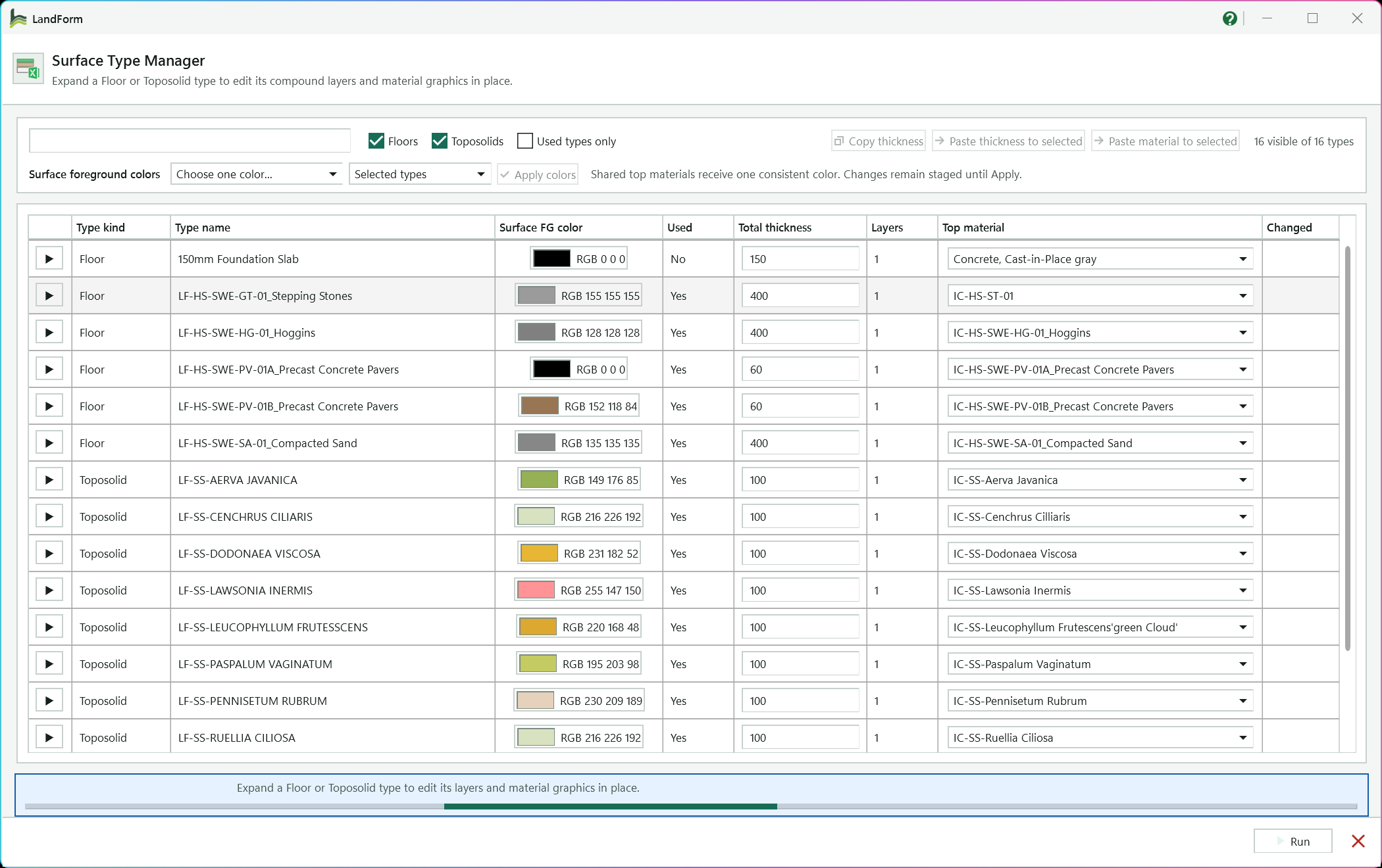
Finds types by name, by kind or by a layer material they use.
Clear a kind to hide it, or tick Used types only to list only types placed in the model.
Shows how many types the current filters leave in the grid.
Click a cell to rename the type.
Click the swatch to set the top material's surface foreground colour.
Type a new depth; finish layers stay as they are and the structural or core layer makes up the difference.
Picks a different material for layer 1.
Shows Yes on rows whose name or layers you have edited.
Opens the row's compound structure layers so you can edit each layer and its material graphics.
Copy a depth or material from one type and paste it to the Ctrl- or Shift-selected rows.
Pick one colour or a random palette, then the scope: Selected types, All visible types or All types.
Stages the chosen colours on the top materials of the target types; nothing is written until Run.
Shows guidance, and names the cell to fix if Run finds a problem.
Checks every staged edit and writes them all to the project in one step.
Open LandForm tab → Management panel → Surface Type Manager.
Filter the grid. Type in the search box to find types by name, by kind or by a layer material they use. Clear Floors or Toposolids to hide that kind, and tick Used types only to list only the types placed in the model. The count on the right shows how many types are visible.
Edit at type level. Click a Type name cell to rename the type, type a new Total thickness, or pick a different Top material for layer 1. Click the Surface FG color swatch to set the top material's surface foreground colour. Rows whose name or layers you edit show Yes under Changed.
A new total thickness keeps the finish layers as they are and adjusts the structural or core layer to make up the difference.
Open the layer editor. Click the arrow at the start of a row. The row expands to show its Compound structure layers: one line per layer, grouped as above core, core or below core.
Edit the layers. For each layer set the function (Func.), Material and thickness (Thick.), and tick Wrap, Struct. or Var. where Revit allows it. Then edit the material itself on the same line: its Name, Render appearance for shading, Shade colour, transparency (Trans.) and the Surface FG, Surface BG, Cut FG and Cut BG patterns, each with its own colour swatch.
Press Unique first if this layer should get its own copy of the material, so the graphic changes do not spread to other types.
Copy and paste between types (optional). To reuse a material, select a layer and press Copy material, then Ctrl- or Shift-click the target type rows and press Paste material to selected. To reuse a build-up depth, select a row, press Copy thickness, select the targets and press Paste thickness to selected.
A pasted material goes onto the active layer of the expanded row and onto layer 1 of every other selected row.
Recolour surfaces in bulk (optional). In the Surface foreground colors row, pick Choose one color... or one of the random palettes, pick the scope (Selected types, All visible types or All types) and press Apply colors.
A single colour is applied once to each top material, so types that share a material stay consistent. A random palette first gives each type its own copy of its top material, then gives each copy a different colour.
Run. Press Run. LandForm checks the staged values, writes everything in one transaction and shows a summary of the types and materials it updated before the window closes.
Every staged change is now in the project: renamed types, new layer structures and thicknesses, reassigned materials, and updated material colours, patterns, transparency and render-appearance settings. Material copies you made with Unique or a random palette exist as new project materials named after the source material and the type. The whole job is one undo step named "LF-Surface Type Manager: Apply Type and Material Changes", and the completion message tells you how many types and materials changed and how many material copies were created.
Search type names, Floor/Toposolid kind, or assigned layer materials.
Show or hide Floor types.
Show or hide Toposolid types.
Limit the grid to types assigned to model elements.
Copy the total thickness of the current type row so you can paste it to other selected rows.
Choose one shared colour, or random greens, greys or beiges for bulk surface foreground colours.
Apply to the selected type rows, every currently visible filtered row, or all types.
Stage the chosen surface foreground colours on the top materials of the target types. Nothing is written until Run.
Review type kind, editable type name, usage, total thickness, layer count, top material, and changed state. Ctrl/Shift-select rows for bulk material paste.
New total thickness for the type. Finish layers stay as they are and the structural or core layer absorbs the difference.
Search or choose the material assigned to layer 1. Revit does not expose its native Material Browser as a value-returning picker.
Copy the material assignment from the active layer.
The compound structure layers of the expanded type. Select a layer to make it the active layer for copying and editing.
Layer function: Structure, Substrate, Thermal / Air, Finish 1, Finish 2, Membrane or Structural Deck.
Material assigned to this layer.
Layer thickness in project length units. Locked at zero for membrane layers.
Let this layer wrap at edges. Only layers outside the core can wrap.
Make this layer the type's structural material. Only one layer per type can be structural.
Make this layer variable in thickness. Only one layer per type can be variable, and not a Structural Deck layer.
Rename the layer's material. The new name applies wherever the material is used.
Use the material's render appearance for shaded display.
Shading transparency of the layer's material, 0 to 100.
Surface foreground pattern of the layer's material, shown with a preview swatch. The swatch button beside it sets its colour.
Surface background pattern of the layer's material. The swatch button beside it sets its colour.
Cut foreground pattern of the layer's material. The swatch button beside it sets its colour.
Cut background pattern of the layer's material. The swatch button beside it sets its colour.
Make this layer material unique before editing project-wide graphics.
Stage a copy of the selected material and assign it only to the selected layer. This side panel is hidden in the current layout; use the layer's Unique button.
Side-panel copy of the layer's material Name field; hidden in the current layout.
Use the render appearance asset for shaded display. Side-panel copy of the layer's Render tick box; hidden in the current layout.
Side-panel copy of the layer's Trans. field; hidden in the current layout.
Side-panel copy of the layer's Surface FG pattern; hidden in the current layout.
Side-panel copy of the layer's Surface BG pattern; hidden in the current layout.
Side-panel copy of the layer's Cut FG pattern; hidden in the current layout.
Side-panel copy of the layer's Cut BG pattern; hidden in the current layout.
Validate every staged edit and write it to the project in one transaction, then close.

Management · Workset Manager
Workset Manager replaces the slow round of Worksets dialog, Properties palette and Visibility/Graphics edits you normally make when a project is first workshared or when a model drifts out of order. Each tab handles one job and works on the rows you tick, so you can review what will change before you press the button. Every button writes its own undo step, and the lists reload afterwards so the Current workset columns always show the model as it is now.
LandForm tab→Management panel→Workset Manager
Button tooltip: “Create, rename, assign, review, and control project worksets.”Workset Manager walkthrough. Until it is published, the steps and the annotated window below walk through the same workflow.
Numbers on the screenshot match the legend. Hover a number or a legend row to highlight the other.
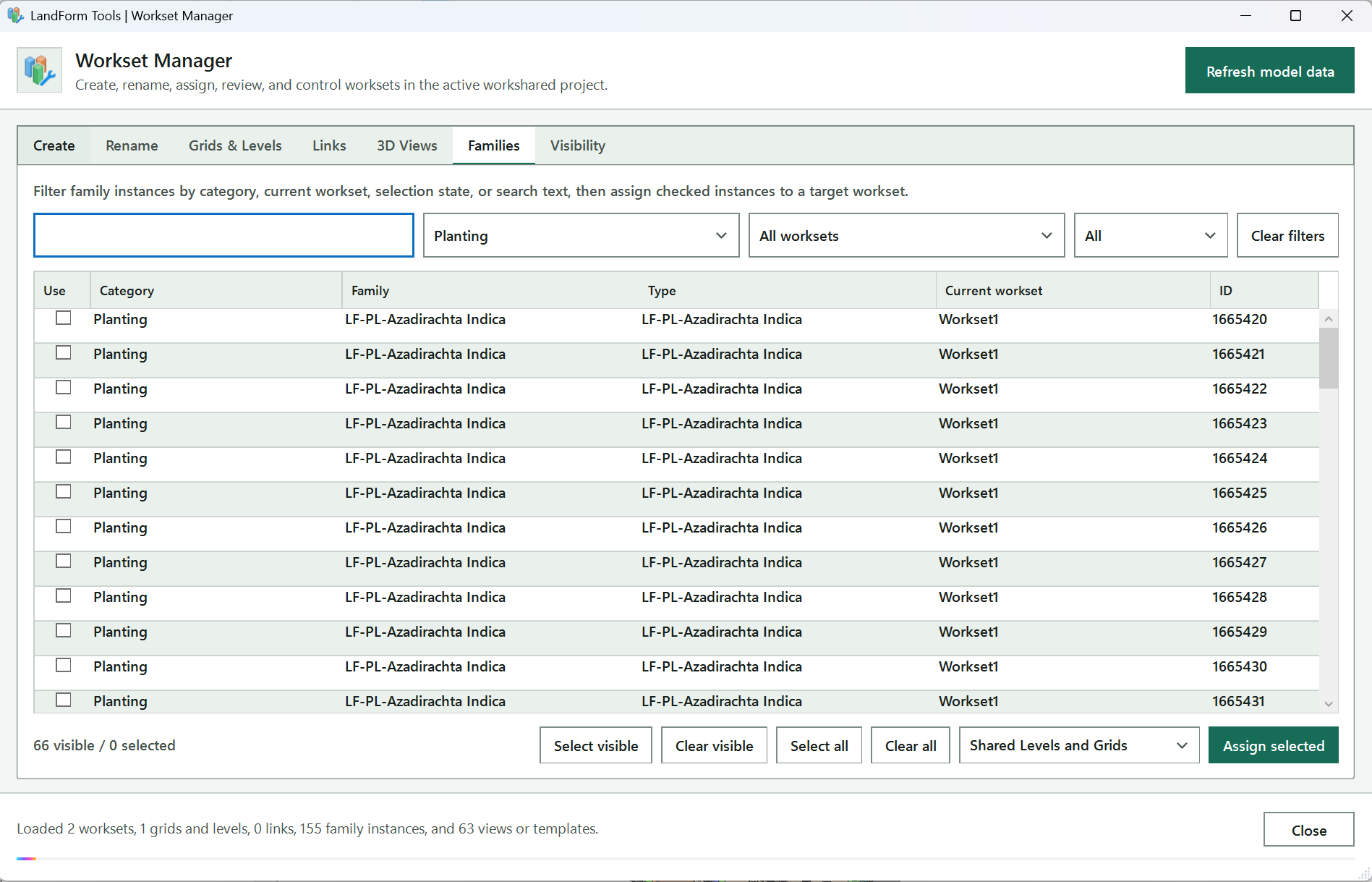
Reports how many worksets, grids and levels, links, family instances and views were found, and what each operation moved or skipped.
Reloads everything from the model; press it after changing the model outside the tool.
Each tab handles one job: Create, Rename, Grids & Levels, Links, 3D Views, Families and Visibility.
Opens a starter text file with one workset name per line; save your edited copy somewhere permanent.
Chooses the text file with one workset name per line and checks each name against the project.
Shows the path of the chosen name list.
Each name from the list as Existing or Missing; missing names are ticked in Create automatically.
Creates the ticked missing worksets in one undo step.
Creates every name marked Missing, whether ticked or not.
Open LandForm tab → Management panel → Workset Manager.
Check what was loaded. The status line reports how many worksets, grids and levels, links, family instances and views were found. Press Refresh model data whenever you have changed the model outside the tool.
Create missing worksets. On Create, press Browse list and choose your text file. Each name is listed as Existing or Missing, and missing names are ticked automatically. Press Create selected for the ticked names or Create all missing for every missing name.
Blank and duplicate lines are ignored, and names that already exist are never created twice.
Rename worksets. On Rename, type the new name in the New name column, tick Use on those rows and press Rename selected worksets. A name that is already taken is skipped.
Place grids and levels. On Grids & Levels, use Show grids and Show levels to filter the list, tick the rows (or press Select visible), choose the target workset and press Assign selected. To move every grid and level in one go, press Assign all to Shared Levels and Grids.
Place links and CAD imports. On Links, tick the Revit links and CAD imports. Choose a target workset and press Assign to target to move them and their types together, or press Create separate worksets to give each link its own workset named with the prefix you typed (LINK_ by default) followed by the link name.
Move family instances. On Families, narrow the list with the search box and the category, workset and selection filters, tick the instances, pick the target workset and press Assign selected.
Make workset 3D views (optional). On 3D Views, tick worksets and press Create combined 3D view for one isometric view showing only those worksets, or Create one view per workset for an isolated view of each. Press Export model breakdown to save a text report of element and category counts per user workset.
Control visibility in views and templates. On Visibility, tick views or templates on the left and worksets on the right. Press Show selected worksets or Hide selected worksets to set their visibility explicitly, or Check visibility to report the current state in the details box without changing anything.
The worksets, names and element assignments you chose are in the model, each operation as its own undo step named after it, for example "LF-Workset Manager: Create Worksets", "LF-Workset Manager: Assign Family Instances" or "LF-Workset Manager: Hide Worksets in Views". New 3D views are named LF_WS_Combined or LF_WS_ followed by the workset name, with only the chosen worksets visible. After every change the lists reload, so the Current workset columns and the status line confirm what moved and what was skipped.
Reload worksets, grids, levels, links, family instances, views, and templates.
Create worksets from a text list of names.
Selected workset list text file.
Choose the text file with one workset name per line and check each name against the project.
Open a starter text file with one workset name per line.
Names from the list with their status, Existing or Missing. Tick Create on the names to add; missing names are ticked automatically.
Create the ticked missing worksets in one undo step.
Create every name marked Missing, whether ticked or not.
Rename user worksets in bulk.
Current and new name of every user workset. Edit New name and tick Use on the rows to rename.
Rename the ticked worksets in one undo step; names already in use are skipped.
Move grids and levels to a workset.
Include grids in the list.
Include levels in the list.
Target user workset for the selected grids and levels.
Tick every row the current filter shows.
Untick every row the current filter shows.
Grids and levels with their kind and current workset. Tick Use on the rows to move.
Move the ticked grids and levels to the target workset.
Assign every grid and level in the project to the standard Shared Levels and Grids workset.
Move Revit links and CAD imports to worksets.
Target workset for a shared assignment.
Prefix added when creating a separate workset for each selected link.
Tick every row in the list.
Untick every row in the list.
Revit links and CAD imports with their kind and current workset. Tick Use on the rows to move.
Move the ticked links and their types to the target workset.
Create a workset named prefix plus link name for each ticked link, then move the link and its type onto it.
Build workset 3D views and the model breakdown report.
User worksets. Tick Use on the worksets to include.
Create one isometric view named LF_WS_Combined with only the ticked worksets visible.
Create an isometric view named LF_WS_ plus the workset name for each ticked workset, showing only that workset.
Export element and category counts for every user workset to a text file.
Move placed family instances to a workset.
Search category, family, type, workset, or element ID.
Show only one category of family instances, or All categories.
Show only instances on one workset, or All worksets.
Show All, only Selected (ticked) or only Unselected rows.
Reset the search text and the three family filters.
Family instances with category, family, type, current workset and element ID. Tick Use on the rows to move.
Untick every family instance, including rows hidden by the filters.
Target workset for checked family instances.
Show, hide or check worksets in views and view templates.
Views and view templates. Tick Use on the ones to change or check.
Visibility check details and operation guidance.
Set the ticked worksets to Show in every ticked view or template.
Set the ticked worksets to Hide in every ticked view or template.
Report, per ticked workset, how many ticked views show it, hide it or use the global setting, without changing the model.
Close Workset Manager.

Management · CleanUp
Revit's own Purge Unused leaves a lot behind: working views nobody placed on a sheet, schedules and legends from old issues, CAD you imported once for tracing, and dozens of import line styles from those drawings. CleanUp, whose window is called Model Purger, gathers all of that into nine categories so you can see what is there, untick anything you need to keep, export a record, and remove the rest in one pass. It is a good last step before you archive a model or hand it over.
LandForm tab→Management panel→CleanUp
Button tooltip: “Review and delete unused project content.”CleanUp walkthrough. Until it is published, the steps and the annotated window below walk through the same workflow.
Numbers on the screenshot match the legend. Hover a number or a legend row to highlight the other.
Scans the project and fills Purge categories; every candidate starts ticked.
Each category with its item count. Click a row to review its items; untick Use to keep the whole category.
Names the chosen category and explains what it contains.
The items of the chosen category; untick Purge on anything that must stay.
Filters the list by name, type or element ID.
Ticks or unticks only the items the search shows.
Saves every analysed candidate with its category, type, element ID and whether it is ticked.
Deletes the ticked items after you confirm, then analyses the model again.
Guides you through the steps and counts the items that could not be deleted.
Open LandForm tab → Management panel → CleanUp.
Analyse. Press Analyze model. LandForm scans the project and fills Purge categories with each category and its item count. Every candidate starts ticked.
Pick a category to review. Click a category row to list its items on the right with their name, type and element ID. The line under the list explains what the category contains.
Keep what you need. Untick Purge on any item that must stay. Untick Use on a category row to keep the whole category; tick it again to select all of its items.
Search within a category (optional). Type in the search box to filter the list by name, type or element ID, then press Select visible or Clear to tick or untick only the filtered items.
Export a record (optional). Press Export CSV to save every analysed candidate with its category, type, element ID and whether it is ticked. The message shows where the file was saved.
Purge. Press Purge N selected and answer Yes to the confirmation, which defaults to No. LandForm deletes the ticked items, then reanalyses the model so the lists show what is left.
The ticked views, schedules, legends, CAD instances, import line styles, rooms, spaces and scope boxes are gone, together with any elements Revit deletes with them. The deletion runs as one transaction named "LF-Model Purger: Delete Selected Items". A message reports how many elements were deleted including dependents; if some items could not be deleted, a warning lists each one with Revit's reason, and the status line counts them. The fresh analysis afterwards confirms what remains.
| Category | What is listed |
|---|---|
| Unplaced Views | Views other than legends and schedules that are not placed on a sheet. The active view and names containing NWC, Navisworks or ACC are protected. |
| Legends | Legend views not placed on a sheet. |
| Schedules | Schedules not placed on a sheet. |
| Imported CAD | DWG or DXF instances embedded in the model. |
| Linked CAD | DWG or DXF link instances. |
| Import Line Styles | CAD layer and object styles under Import Object Styles. |
| Unplaced Rooms | Rooms with no location and no measurable area. |
| Unplaced Spaces | Spaces with no location and no measurable area. |
| Unused Scope Boxes | Scope boxes not used by any view's Scope Box parameter. |
Scan the active project and refresh all Model Purger candidates.
Purge categories with their item counts. Click a row to review its items; untick Use to keep the whole category.
Search the selected category by name, type, or Revit element id.
Tick every item the search currently shows in the selected category.
Untick every item the search currently shows in the selected category.
Items in the selected category with name, type and element ID. Untick Purge on anything to keep.
Export every analyzed candidate and its current selection state to CSV.
Delete the checked candidates after confirmation, then refresh the analysis.
Close Model Purger.

Management · Pin · Viewports
Once sheets are composed and views are aligned, a stray drag is all it takes to move a viewport. Pin > Viewports scans the whole project, pins each viewport that is not pinned yet, and reports what it did. There is no window to fill in and nothing to select first.
LandForm tab→Management panel→Pin ▾→Viewports
Button tooltip: “Pin all viewport elements in the project.”Viewports walkthrough. Until it is published, the steps and the annotated window below walk through the same workflow.
Open LandForm tab → Management panel → Pin ▾ → Viewports.
Run the command. Press Viewports in the Pin pulldown. LandForm immediately collects every viewport on every sheet and pins the ones that are free.
Read the summary. A dialog reports how many viewports were found, how many were pinned now, how many were already pinned and how many failed. If anything failed, the dialog appears as a warning and lists up to five failures with the element name and ID.
Close the dialog. The sheets are ready; pinned viewports show Revit's pin icon when selected.
Every viewport in the project is pinned, so Revit asks before letting anyone move it. The change is a single undoable step named "LF-Pin Viewports". Viewports that were already pinned are counted but not touched, so running the tool again is harmless.
No separate LandForm window. This command runs directly from Revit selection and prompts; follow the workflow above and the messages shown beside the cursor or on Revit's status bar.

Management · Pin · CAD Links
A linked DWG that slides a few millimetres puts every setting-out dimension in doubt. Pin > CAD Links scans the project for linked CAD instances, pins each one that is not pinned yet, and reports the counts. There is no window to fill in and nothing to select first.
LandForm tab→Management panel→Pin ▾→CAD Links
Button tooltip: “Pin all linked CAD instances in the project.”CAD Links walkthrough. Until it is published, the steps and the annotated window below walk through the same workflow.
Open LandForm tab → Management panel → Pin ▾ → CAD Links.
Run the command. Press CAD Links in the Pin pulldown. LandForm collects every linked CAD instance in the project and pins the ones that are free.
Read the summary. A dialog reports how many CAD links were found, how many were pinned now, how many were already pinned and how many failed. If anything failed, the dialog appears as a warning and lists up to five failures with the element name and ID.
Close the dialog. The links are locked in place; a pinned link shows Revit's pin icon when selected.
Every linked CAD instance in the project is pinned, so Revit asks before letting anyone move it. The change is a single undoable step named "LF-Pin CAD Links". Links that were already pinned are counted but not touched, so running the tool again is harmless.
No separate LandForm window. This command runs directly from Revit selection and prompts; follow the workflow above and the messages shown beside the cursor or on Revit's status bar.

Management · Pin · RVT Links
Pin > RVT Links scans the project for Revit link instances, pins each one that is not pinned yet, and reports the counts. If a link is placed more than once, every placed copy is included. There is no window to fill in and nothing to select first.
LandForm tab→Management panel→Pin ▾→RVT Links
Button tooltip: “Pin all Revit link instances in the project.”RVT Links walkthrough. Until it is published, the steps and the annotated window below walk through the same workflow.
Open LandForm tab → Management panel → Pin ▾ → RVT Links.
Run the command. Press RVT Links in the Pin pulldown. LandForm collects every Revit link instance in the project and pins the ones that are free.
Read the summary. A dialog reports how many RVT links were found, how many were pinned now, how many were already pinned and how many failed. If anything failed, the dialog appears as a warning and lists up to five failures with the element name and ID.
Close the dialog. The links are locked in place; a pinned link shows Revit's pin icon when selected.
Every Revit link instance in the project is pinned, so Revit asks before letting anyone move it. The change is a single undoable step named "LF-Pin RVT Links". Instances that were already pinned are counted but not touched, so running the tool again is harmless.
No separate LandForm window. This command runs directly from Revit selection and prompts; follow the workflow above and the messages shown beside the cursor or on Revit's status bar.

Management · Pin · All Links
Pin > All Links combines the RVT Links and CAD Links commands: it scans the project for Revit link instances and linked CAD instances, pins each one that is not pinned yet, and reports the counts together. Sheet viewports are not included; use Pin > Viewports for those. There is no window to fill in and nothing to select first.
LandForm tab→Management panel→Pin ▾→All Links
Button tooltip: “Pin all linked CAD and Revit instances in the project.”All Links walkthrough. Until it is published, the steps and the annotated window below walk through the same workflow.
Open LandForm tab → Management panel → Pin ▾ → All Links.
Run the command. Press All Links in the Pin pulldown. LandForm collects every Revit link instance and every linked CAD instance in the project and pins the ones that are free.
Read the summary. A dialog reports how many links were found, how many were pinned now, how many were already pinned and how many failed. If anything failed, the dialog appears as a warning and lists up to five failures with the element name and ID.
Close the dialog. The links are locked in place; a pinned link shows Revit's pin icon when selected.
Every linked Revit model and linked CAD file in the project is pinned, so Revit asks before letting anyone move them. The change is a single undoable step named "LF-Pin All Links". Links that were already pinned are counted but not touched, so running the tool again is harmless.
No separate LandForm window. This command runs directly from Revit selection and prompts; follow the workflow above and the messages shown beside the cursor or on Revit's status bar.
LandForm ribbon panel
Turn CAD linework, hatches, text and blocks into Revit elements and families.

CAD · CAD · AutoCAD Block To Family
Planting plans, lighting layouts and furniture schemes often arrive as a DWG in which every tree, bollard or bench is a block. Instead of placing hundreds of families by hand, you pick the import, let Smart Map pair each block name with a loaded family type, correct the rows that need it and press Run. Every instance lands on the block's insertion point, turned to the block's rotation and lifted to the block's own elevation, so the Revit model takes over exactly where the CAD left off.
LandForm tab→CAD panel→CAD ▾→AutoCAD Block To Family
Button tooltip: “Place Revit families from CAD block references.”AutoCAD Block To Family walkthrough. Until it is published, the steps and the annotated window below walk through the same workflow.
Numbers on the screenshot match the legend. Hover a number or a legend row to highlight the other.

Click the CAD import or link whose block references should become families.
Shows the name of the picked drawing.
Reports how many block names were found, warns about problems and shows the final count; here the project has no CAD link or import yet.
Opens the Block Mapping panel and runs Smart Map; correct a row's family type or untick Use to skip a block.
Mapping counter, which reads "N/N mapped · N inst" once blocks are mapped.
Level the placed instances are hosted on.
Height in metres added above each block's elevation.
Places one family instance per mapped block reference in one undoable step.
Open LandForm tab → CAD panel → CAD ▾ → AutoCAD Block To Family.
Pick the drawing. Press Pick CAD and click the CAD import or link in the view. The toolbar shows its name and the status line reads "Found N CAD block name(s)".
If the drawing holds no block references the status says so; the symbols were probably exploded before the file reached you.
Open the mapping. Press Map. The Block Mapping panel lists every block name with its instance Count, and Smart Map runs automatically, scoring the words shared between the block name and each family and type name.
A block whose name matches nothing is given the first family in the list, so read every row rather than trusting the counter alone.
Correct the rows. Change the Revit Family Type drop-down on any row, or untick Use to leave that block unplaced. For a long family list press Families, choose a category, type part of a name, then drag the type onto a row or double-click it for the row you selected last.
The toolbar counter updates to "N/N mapped · N inst" as you go.
Set the level and height. Choose the Level and type an Offset in metres. Each instance is placed at its block's elevation plus this offset.
Run. Press Run. The progress bar counts through the blocks and the status line finishes with "Block complete. Created: N. Skipped: N."
The model now holds one family instance for every block reference whose name was ticked and mapped, each sitting on the block's insertion point, rotated to the block's X direction and hosted on the chosen level. The whole placement is a single undoable step named "LF-AutoCAD Block To Family: Place Block Families". The Skipped count covers block references on unmapped or unticked names and any instance Revit refused to create. Your mappings, level and offset are saved and reloaded the next time you open the tool.
LF-PL-Delonix Regia) match far more reliably than generic names.Returns to Revit so you can click the CAD import or link whose block references should become families.
Limits the run to one block name, or All blocks. Not shown in the current toolbar, so every mapped block is placed.
Shows or hides the Block Mapping panel; opening it runs Smart Map automatically.
Level the placed family instances are hosted on.
Height in metres added above each block's elevation. Long-press and drag vertically to scrub the value.
Choose the fallback family type. Only loadable model families that can be placed at a point are listed; tags, title blocks, detail items, in-place families and curve-driven families such as beams are left out.
Turns each instance to match the block's rotation. Not shown in the current toolbar and always on.
Places each instance at the block's own elevation instead of the level. Not shown in the current toolbar and always on.
Places one family instance per block reference that has an enabled mapping, in one undoable step.
Re-matches every block name to the loaded family type with the most similar name.
Shows or hides the family browser beside the mapping rows.
Narrow the family browser to one model category, or keep All Categories.
Filters the family browser to names containing the text you type.
Model family types that match the category and search. Drag one onto a mapping row, or double-click it for the selected CAD block.

CAD · CAD · Set Type By Text
Planting and paving plans label their areas with codes such as ACA OER or PAVING 01. Once you have made the surfaces (with Hatch, Line Tracer or Hatch To Floor / Toposolid), this tool reads the CAD Text and MText, lists every unique value with how often it appears, and lets you map each value to an existing type or to a new type named from the text. Press Run and each surface whose top face contains a label point switches to the mapped type, in one undoable step with its own Undo.
LandForm tab→CAD panel→CAD ▾→Set Type By Text
Button tooltip: “Assign floor or toposolid types from CAD text labels.”Set Type By Text walkthrough. Until it is published, the steps and the annotated window below walk through the same workflow.
Numbers on the screenshot match the legend. Hover a number or a legend row to highlight the other.

Click the CAD import or link whose Text and MText labels should be read.
Reads the drawing's text again instead of reusing the copy cached earlier in the session.
Tick to retype Toposolids; leave it clear to retype Floors.
Reloads the project's Floor or Toposolid types after you have added new ones.
Opens the workspace with the CAD Text list, the Text Mapping grid and the type browser.
Builds new types named from the CAD text instead of assigning existing ones.
Sets the text placed before and after the CAD value in each new type name.
Preview of a new type name built with the current naming rule.
In Auto Create mode, gives each new type its own material coloured from the chosen palette.
Switches every surface with a mapped label on its top face to the mapped type, in one undoable step.
Puts back the previous type of every surface the last run changed.
Status line; here it warns that there is no CAD drawing to pick, and after a pick it reports how many text values were read.
Open LandForm tab → CAD panel → CAD ▾ → Set Type By Text.
Pick the drawing. Press Pick CAD and click the CAD import or link. LandForm exports the drawing on its own to a temporary DXF, reads every Text and MText entity and reports "Read N unique CAD text value(s)".
If the tool was used on this drawing earlier in the session, the cached text is reused and the status says so; press Read Text to read it again.
Choose the target. Leave Toposolid clear to retype Floors, or tick it to retype Toposolids. Press Refresh if you have just added types to the project.
Open the workspace. Press Map. The CAD Text list on the left shows each value with its count, the Text Mapping grid sits in the middle, and the type browser on the right lists the project's Floor or Toposolid types with a search box.
Add rows. Select a value and press Add (double-clicking a value does the same), or press Add All for a row per value. If a type is selected in the browser when you press Add, it is assigned at once.
Assign existing types. Press Smart Find to match each row to the type with the most similar name, including botanical codes such as AER JAV for Aerva javanica. Rows with no match stay unassigned and are highlighted red for you to finish by hand: pick from the row's Revit Type drop-down, drag a type from the browser onto a row, or select rows and double-click a type.
Or create new types. Tick Auto Create. Press Naming to set the text placed before and after the CAD value (the default makes LF-ACA OER) and watch the preview. The grid now shows New Type Name per row and the browser lists Floor Templates or Toposolid Templates: Smart Find picks a template for each row, and you can drag another onto any row. Tick Random color and choose a palette to colour each new type's material; click a colour cell to change one. Create Types builds or reuses the types now so you can inspect them before running.
Run. Press Run. LandForm collects every Floor or Toposolid, finds the label whose insertion point lies on each surface's top face, and switches the surface to the mapped type. A summary reports how many type changes were applied, how many new types were created and how many matched labels had no mapping row.
Undo if needed. Press Undo on the toolbar to put back the previous type of every surface the last run changed; the status reads "Restored N type assignment(s)".
Every Floor or Toposolid that contains a mapped label now carries that label's type, changed in one undoable step named "LF-Set Type By Text: Set Types from CAD Text". In Auto Create mode the new types are duplicates of their template named from your rule, created in "LF-Set Type By Text: Create Types from CAD Text", and with Random color each has its own coloured material. Surfaces with no label, and labels with no mapping row, are left untouched and counted in the summary. Undo reverses the last run as "LF-Set Type By Text: Undo Set Types".
Pick the CAD import/link that contains the source text.
Export the active view to DXF temporarily and read CAD Text/MText values.
Expand the text-to-type mapping workspace.
When checked, mapping rows update Toposolid types instead of Floor types.
Reload available Revit floor or toposolid types from the active document.
Create missing Floor/Toposolid types from the selected base type and the CAD text value.
In Auto Create mode, gives each new type its own material coloured from the palette and shows the Color column.
Color Rules palette the new type colours are taken from; Teal (green tones) by default.
Set how new Floor/Toposolid types are named.
Create or reuse the generated Floor/Toposolid types, then populate the mapping rows.
Undo the type changes from the last Apply.
Apply the mapping rows to matching floors or toposolids.
Every unique CAD text value with its count. Select one for Add, or double-click it to add its row.
Add a row from the selected CAD text. If a Revit type is selected, it is assigned too.
Add mapping rows for every loaded CAD text value.
Match CAD text rows to similar Revit type names.
Clear all mapping rows.
The mapping rows: CAD Text, Revit Type or New Type Name, Color, and a cross to remove the row. Drop a type onto a row to assign it.
Revit Type drop-down in each row; the type the surfaces under that text receive.
Search Revit types.
Project Floor or Toposolid types, or templates in Auto Create mode. Drag onto a row or double-click for the selected rows.
Text added before each CAD text value.
Example CAD text used for the preview only.
Text added after each CAD text value.
Closes the window without changing the naming rule.
Saves the naming rule and renames the pending Auto Create rows with it.

CAD · CAD · Hatch To Floor / Toposolid
Landscape CAD plans carry their surfaces as hatches: lawn on one layer, paving on another, planting beds on a third. This tool reads those hatch faces, groups them by layer, and either assigns each layer an existing Floor or Toposolid type or duplicates a template type once per layer, optionally with its own material colour. One press of Run then builds a clean, editable surface from every closed hatch boundary.
LandForm tab→CAD panel→CAD ▾→Hatch To Floor / Toposolid
Button tooltip: “Create floors or toposolids from CAD hatch boundaries.”Hatch To Floor / Toposolid walkthrough. Until it is published, the steps and the annotated window below walk through the same workflow.
Numbers on the screenshot match the legend. Hover a number or a legend row to highlight the other.
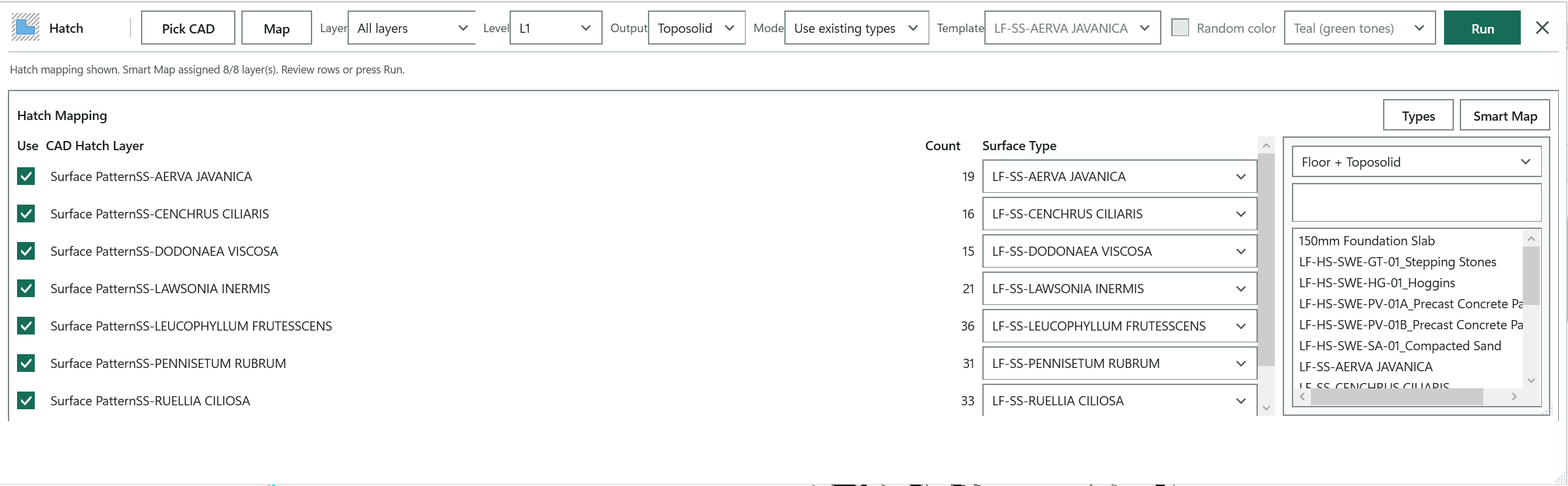
Click the CAD import whose hatches you want to convert.
Reports how many hatch faces were found and the run totals; here it warns that the project has no CAD drawing to pick.
Converts one CAD hatch layer, or All layers.
Base level for the new surfaces.
Creates Toposolid or Floor elements.
Use existing types maps each layer to a type; Create new types duplicates the template once per layer.
Opens one row per hatch layer and runs Smart Map to fill each row's surface type.
The Floor or Toposolid type duplicated for each layer in Create new types mode.
Gives each new type its own material colour from the chosen palette.
Creates one surface from every closed hatch boundary in one undoable step.
Open LandForm tab → CAD panel → CAD ▾ → Hatch To Floor / Toposolid.
Pick the drawing. Press Pick CAD and click the CAD import. The status line reports how many hatch faces were found and the Layer list fills with the layers they use.
Choose the output. Set Level, pick Toposolid or Floor under Output, and choose the Mode.
Map layers to existing types. With Use existing types selected, press Map. One row appears per hatch layer and Smart Map fills the Surface Type of each from the type whose name shares the most words with the layer, preferring the Output kind. Fix any row from its drop-down, or press Types, filter and search, then drag a type onto the row or double-click it. Untick Use on layers you do not want converted.
Or create a type per layer. Switch Mode to Create new types and pick the Template type. Each row now shows a New type name box (the layer name by default) that you can edit; a name that clashes or is empty is outlined until you fix it. Tick Random color and choose a Palette to give each new type its own material colour, and click any colour cell to pick a different colour for that layer.
Run. Press Run. The progress bar steps through the hatches and the status line ends with "Hatch complete. Created: N. Skipped: N."
The model now contains one Floor or Toposolid per closed hatch boundary, on the chosen level, each carrying the type its layer was mapped to. In Create new types mode the new types are duplicates of the template named after the layer (or your edited name), and with Random color each has its own duplicated material with the palette colour applied to its shading and patterns; a type that already exists under that name is reused rather than duplicated. The whole run is one undoable step named "LF-Hatch To Floor / Toposolid: Create Floors / Toposolids". Hatches whose boundary did not form a usable closed profile are counted as Skipped.
Select the CAD import that contains hatch boundaries.
Show inline hatch mapping and run Smart Map.
Choose a CAD hatch layer, or All layers.
Base level for the created surfaces.
Create Toposolids or Floors from the selected hatch profiles.
Use mapped existing types, or duplicate a template into new types.
Floor or Toposolid type to duplicate when creating colored output types.
Duplicate the selected template type and its material for each CAD hatch layer, then assign a palette color.
Color Rules palette used for duplicated materials.
Create surfaces from the selected CAD hatch geometry.
Automatically match hatch layers to Floor or Toposolid types.
Show or hide the Floor/Toposolid type browser for drag/drop mapping.
Filter by output type: Floor or Toposolid.
Search Floor or Toposolid type names.
Drag a Floor or Toposolid type onto a hatch layer row, or double-click to assign it to the selected row.

CAD · CAD · Detail Converter
Office standard details usually live as DWGs full of layers named for pen weights. Detail Converter reads the import in your drafting or detail view, matches each layer to a line style (by name first, then by the weight words such as THIN, MEDM, HVY and HIDDEN), previews every style at its real weight and dash pattern, and converts lines, hatches and text in one run. CAD hatch patterns come across as drafting fill patterns and filled region types of their own, so you do not need the original .pat files.
LandForm tab→CAD panel→CAD ▾→Detail Converter
Button tooltip: “Convert CAD detail linework, hatch, and text into Revit elements.”CADLayers and RevitLineStyle columns, or a few minutes to make one with Template.Detail Converter walkthrough. Until it is published, the steps and the annotated window below walk through the same workflow.
Numbers on the screenshot match the legend. Hover a number or a legend row to highlight the other.

Click the CAD import or link that holds the detail.
Counts the layers found, summarises the run, and here says the project needs a linked or imported CAD drawing first.
Opens the layer mapping panel and runs Smart Map to match each CAD layer to a line style.
Converts mapped CAD linework into Detail lines or Model lines.
Converts closed CAD hatches into filled regions, of the region type chosen here when Auto is off.
Rebuilds each CAD hatch pattern as its own filled region type.
Converts CAD Text and MText into text notes of the chosen type.
Converts the picked detail with the current mapping in one undo step.
Adds a straight leader to every selected text note that has none.
Click a note, then where its arrow should land; the elbow stays orthogonal.
Open LandForm tab → CAD panel → CAD ▾ → Detail Converter.
Pick the detail. Press Pick CAD and click the import or link. Its name appears on the toolbar and the status line counts the layers it found.
Map layers to line styles. Press Map. The Layer Mapping panel lists one row per CAD layer and Smart Map runs at once, preferring a style that shares a whole word with the layer name and otherwise falling back to the weight words your CAD standard uses. Each row previews its style at the style's own weight, colour and dash pattern. Click a row to draw that layer's CAD linework on screen in the row's colour so you can see what it covers.
Untick Use on a layer you do not want converted. Smart Map leaves Revit's bracketed boundary, separation and sketch styles alone.
Fix rows by hand. Change a row's style from its drop-down, or press Styles to open the line style browser, search for a style, then drag it onto a row or double-click it for the selected row.
Or drive the run from a workbook. Tick Use workbook. Press Template to write a starter workbook from the picked layers and this project's line styles and open it, edit its CADLayers and RevitLineStyle columns, then press Import to load the rows back in. Browse picks an existing workbook.
Choose what to convert. Tick Lines and choose Detail lines or Model lines; tick Hatch and either leave Auto on or clear it and pick a single Region Type; tick Text and choose the Text Type for converted Text and MText.
Model lines need a view with a work plane; detail lines, filled regions and text need an annotation view.
Review the hatch patterns. With Auto on, the CAD Hatch Patterns section lists every pattern found in the detail with a drawn preview. Edit the New type prefix (LF-PATT- by default), rename the types that will be created, untick patterns you do not want, and click a row to shade every hatch that uses that pattern on screen.
Run. Press Run. When text or automatic patterns are involved the tool first exports the detail to read them, then converts. Curves are grouped by target style and created in batches, and the status line summarises the result: "Lines: N. Filled regions: N. Text notes: N", how many regions matched their CAD pattern, which patterns were matched to the closest project pattern instead, and how many curves were skipped on unmapped layers.
Finish the leaders. CAD leaders rarely survive the export, so their linework arrives as lines. Select the text notes that need a leader and press Leader to add a straight leader to each, then press Leader End, click a note and click where its arrow should land; the elbow stays orthogonal. Keep picking notes and press Esc to finish.
The view now contains native detail or model lines in the mapped line styles, filled regions in types named after their CAD patterns (or the single region type you chose), and text notes in the chosen text type, all placed where the CAD geometry was. The conversion is one undoable step named "LF-Detail Converter: Convert CAD Details"; leaders you add afterwards are separate steps named "LF-Detail Converter: Add Leaders" and "LF-Detail Converter: Place Leader End". Generated fill patterns and region types carry your prefix so they sort together, and an existing project pattern or region type of the same name is reused instead of duplicated.
A-DETL-HIDDEN becomes the hidden style rather than falling through to thin.Select the CAD import that holds the typical detail.
Show the CAD layer to Revit line style mapping and run Smart Map.
Convert mapped CAD linework into Revit curves.
Create view-specific detail lines, or model lines on the view sketch plane.
Convert closed CAD hatch boundaries into filled regions.
Filled region type used for every converted CAD hatch. Not used while Auto is on, because the type then comes from the CAD pattern.
Rebuild each CAD hatch pattern as its own filled region type, named after the CAD layer. Clear this to place every region with the type on the left.
Convert CAD Text and MText into Revit text notes.
Text note type used for converted CAD text.
Add a straight leader to every selected text note that has none.
Pick a text note and its leader endpoint. The elbow stays orthogonal.
Convert the selected CAD detail using the current mapping.
Automatically match each CAD layer to the closest Revit line style.
Show or hide the line style browser for drag/drop mapping.
Run the conversion from the mapping workbook instead of the rows below.
Workbook holding the CADLayers and RevitLineStyle columns.
Select an existing mapping workbook.
Write a starter workbook from the picked CAD layers and this project's line styles, then open it.
Load the workbook rows into the mapping rows below.
Search Revit line style names.
Drag a line style onto a CAD layer row, or double-click to assign it to the selected row.

CAD · CAD · Toposolid From CAD
Survey contours and spot levels usually reach you as a DWG. Instead of exporting to a points file, you pick the link, tick the layers that carry elevations, choose a level and Toposolid type and press Run. LandForm samples the curves at the spacing you set, removes duplicate plan positions Revit cannot accept, and keeps every surviving point editable. If Revit refuses a point set it retries with simplified linework, and a DirectShape option builds a plain mesh when the terrain is denser than a Toposolid can hold.
LandForm tab→CAD panel→CAD ▾→Toposolid From CAD
Button tooltip: “Create a toposolid from CAD link curves.”Toposolid From CAD walkthrough. Until it is published, the steps and the annotated window below walk through the same workflow.
Numbers on the screenshot match the legend. Hover a number or a legend row to highlight the other.

Click the CAD link or import; its name replaces "No CAD selected".
Reports what the pick found and warns about problems; here the project has no CAD link or import yet.
Tick the layers that carry elevations, or leave All layers ticked.
Base level for the Toposolid.
Toposolid type for the new surface.
Builds a plain terrain mesh instead, with no point limit but not editable as terrain.
Inserts extra points along each curve at this spacing, 5 m by default.
Redraws the point preview and refreshes the point counter without changing the model.
Creates the Toposolid, or the DirectShape, from the ticked layers.
Open LandForm tab → CAD panel → CAD ▾ → Toposolid From CAD.
Pick the drawing. Press Pick CAD and click the link or import. The toolbar shows its name, the status line reports how many point or curve source objects it found, and the Layer list fills.
Tick the layers. Open Layer and tick one or more layers, or leave All layers ticked. The closed box reads the single layer name or "N layers". Ticking only the contour and spot-level layers keeps building outlines and text out of the surface.
Choose the output. Set the Level and the Toposolid Type. Tick DirectShape instead if you want a plain terrain mesh that follows the spacing exactly and has no point limits, at the cost of not being editable as terrain.
Set the density. Tick Subdivide and type a Spacing (m) (5 m by default) to insert extra points along each curve. Smaller spacing follows curves more closely but multiplies the point count.
Read the preview. Points are drawn in the view as soon as you change a setting, and the counter on the right of the status bar shows how many points Run will request; press Preview to redraw it. A very dense setting shows "~N points" instead of drawing, a flat selection is called out in the status line, and from 100,000 points the status warns that Revit will be slow.
Run. Press Run. The status line finishes with the number of CAD source objects and points used, the elevation range from lowest to highest point, how many duplicate plan positions were removed and how many points had unusable coordinates.
A Toposolid of the chosen type now sits on the level with one editable shape point for every sampled CAD vertex, created in one undoable step named "LF-Toposolid From CAD: Create Toposolid" (or "LF-Toposolid From CAD: Create Terrain Shape" for a DirectShape). The reported elevation range tells you at once whether the drawing carried real heights. If Revit rejected the full point set, the message explains that shape-redundant vertices were dropped and how far the kept linework deviates from the CAD, so you know what was simplified.
Select the CAD link or import that contains the curves.
Drop-down of CAD layers with a tick box each; the closed box reads the layer name or "N layers".
Tick box beside each layer in the list. All layers excludes the specific layers and vice versa; nothing ticked falls back to All layers.
Base level for the created toposolid.
Toposolid type for the created surface.
Build the terrain as a DirectShape mesh instead of a toposolid. Handles any point count and follows the spacing exactly, but the result is plain geometry, not editable terrain.
Insert extra points along each curve at the given spacing for a denser toposolid.
Maximum distance between subdivided points, in metres (5 by default). Must be a positive number.
Redraws the point preview in the view and refreshes the point counter without changing the model.
Create a toposolid (or DirectShape) from the ticked CAD layers with the current settings.

CAD · CAD · SketchUp Import(BETA)
Concept design often happens in SketchUp and then has to be redrawn in Revit. SketchUp Import reads the file directly, with no intermediate export, and shows you a mapping of its groups, painted materials and components. You decide what each becomes: a Toposolid (with a type created from the SketchUp material and colour if you like), a DirectShape in a Revit category, a loaded family type, or a family generated from the component geometry itself. Press Run and the concept lands in Revit at its true positions and rotations, ready for detailed design.
LandForm tab→CAD panel→CAD ▾→SketchUp Import(BETA)
Button tooltip: “Import SketchUp concept terrain and planting.”binaries\sketchup\x64 folder copied next to the LandForm add-in. Open SKP checks at once and tells you exactly which file is missing..skp file, a Toposolid type and Level for the terrain, and any families you want components mapped to already loaded. Toposolids need Revit 2024 or later.SketchUp Import (BETA) walkthrough. Until it is published, the steps and the annotated window below walk through the same workflow.
Numbers on the screenshot match the legend. Hover a number or a legend row to highlight the other.

Choose the .skp file; it is read in the background.
Gives the next step, then how many groups, components and instances the file holds, and the run summary.
The Toposolid type used for the terrain.
The level the terrain and components are built on.
Metres added to the SketchUp elevations.
Opens the SketchUp Mapping panel for groups, materials and components.
Builds the terrain, then the shapes, then places the components.
Open LandForm tab → CAD panel → CAD ▾ → SketchUp Import(BETA).
Open the file. Press Open SKP and choose the .skp. The model is read in the background and the status line reports how many groups and components it holds and how many component instances.
If the file cannot be read, a dialog explains why; a version mismatch is usually fixed by resaving the model in SketchUp.
Set the terrain defaults. Choose the Toposolid Type, the Level and an Offset in metres added to the SketchUp elevations.
Open the mapping. Press Map. The SketchUp Mapping panel shows three sections, each with a count and a Set all... box that applies one choice to every row.
Decide what each group becomes. In Groups & Geometry set each row to Skip, Toposolid, DirectShape (and pick its Revit category) or By Material, which pools the group's faces by their painted material into the next section.
Map the materials. In Materials (from groups set to By Material) set each material to Skip, Toposolid or DirectShape. A Toposolid row can use an existing type or (Auto — from material), which creates a type named after the toolbar type and the material with a matching Revit material in the SketchUp colour.
Map the components. In Components tick the ones to place and pick a family type, or choose (Auto — create from SketchUp geometry) to generate a loadable family from the component itself. Smart Map matches components to loaded families by name; Set all... offers Enable all, Disable all and Auto-create unmapped.
Set the placement options. Keep Match rotation and Use SKP elevation on to reproduce each instance exactly. Tick Top surfaces only when DirectShapes should keep just the visible finish surfaces and drop walls and risers; Toposolids always use top faces.
Run. Press Run. Terrain is built first, then shapes, then components, and the status line summarises "Toposolids: N (points). Shapes: N. Placed: N. Generated types: N. Skipped: N." with the first warning.
Each mapped group or material is now a Toposolid whose boundary was traced from the mesh, with every disjoint patch its own cleanly bounded surface, or a DirectShape per material in the chosen category. Components stand at their SketchUp positions and rotations as the families you mapped or as new generated families. The work is split into undo steps named "LF-SketchUp Import: Create Terrain", "LF-SketchUp Import: Create Shapes", "LF-SketchUp Import: Create Types", "LF-SketchUp Import: Create Component Family" and "LF-SketchUp Import: Place Families". Every warning is appended to SketchUpImport-warnings.log in the LandForm folder of your Windows temp directory, and the summary names it.
No separate LandForm window. This command runs directly from Revit selection and prompts; follow the workflow above and the messages shown beside the cursor or on Revit's status bar.

CAD · Hatch · Hatch
When a CAD plan arrives with paving, lawns and beds drawn as outlines rather than hatches, Hatch is the fastest way to turn them into Revit surfaces one by one. You choose the output type, level and height once, press Pick and click inside each enclosed region while a preview outlines the area under your cursor. The CAD geometry is read once and kept between picks, so each click is instant, and All converts every detected region in one go.
LandForm tab→CAD panel→Hatch ▾→Hatch
Button tooltip: “Create floors or toposolids by clicking inside closed CAD linework.”Hatch walkthrough. Until it is published, the steps and the annotated window below walk through the same workflow.
Numbers on the screenshot match the legend. Hover a number or a legend row to highlight the other.

Floor or Toposolid; the Type list follows this choice.
The floor or toposolid type for the created surfaces.
The level the surfaces are hosted on, and the elevation at which the CAD regions are read.
Height above the level, written to each surface as its height offset.
Keeps the CAD's true arcs and circles in the boundary instead of short segments.
Click inside closed CAD regions one by one while a preview outlines the area under the cursor; Esc finishes.
Tells you the next step, warns when there is no CAD to read, and counts the surfaces created.
Works like Pick but cleans each boundary first; use it on overlapping or doubled linework.
Turns every detected closed region into a surface after you confirm.
Open LandForm tab → CAD panel → Hatch ▾ → Hatch.
Choose the output. Set Output to Floor or Toposolid, pick the Type (foundation slabs are hidden from the floor list), the Level and the Z (m) height offset above it. Tick Arcs to keep the CAD's true arcs and circles in the created boundary instead of short segments.
Press Pick. If no CAD import is selected, Revit asks you to click the import containing the closed boundaries. LandForm reads every closed region once and reports how many it retained.
Click inside regions. Hover over an enclosed area and its outline is previewed on screen; click to create the surface. Keep clicking other regions; the status line counts what you have created. Press Esc to finish.
Trace works the same way and cleans each boundary before it is created; use it for drawings with overlapping or doubled linework.
Or convert everything. Press All, confirm the prompt, and every detected closed region becomes a surface. Complex, open or self-intersecting boundaries that Revit rejects are skipped and counted.
Each region you picked is now a Floor or Toposolid of the chosen type on the chosen level, with its Height Offset From Level set to your Z (m) value, and the created elements are left selected so you can check them. Each pick is committed as an undoable step named "LF-Hatch: Create Floors / Toposolids", and the status line reports "Created N hatch surface(s)" with any skipped count. Your output, type, level, offset and arcs settings are remembered for the next session.
Floor or Toposolid output; the Type list follows this choice.
Floor or Toposolid type for the created surfaces. Foundation slab types are left out.
Level the created surfaces are hosted on; also the elevation at which the CAD regions are read.
Z (m): height above the level, written to each surface as Height Offset From Level.
Keep the CAD's real arcs and circles in the created boundary instead of short line segments.
Create every detected closed CAD region.
Keep clicking inside CAD regions to clean and create them; press Esc to finish.
Pick inside closed CAD regions one by one.
Close Hatch.

CAD · Hatch · Line Tracer
Line Tracer is the batch version of Hatch. It opens as the Hatch Studio window over your Revit view and shows the drawing's linework with every detected closed region tinted. You hover, click and box-select regions, close gaps in the CAD by drawing lines or arcs, give each CAD hatch layer its own output type, and even turn a run of regions into a flight of steps. One press of Convert builds everything in one Revit transaction, and regions that already have a surface are marked so you never create them twice.
LandForm tab→CAD panel→Hatch ▾→Line Tracer
Button tooltip: “Select many closed CAD regions on a canvas, then create them all at once.”Line Tracer walkthrough. Until it is published, the steps and the annotated window below walk through the same workflow.
Numbers on the screenshot match the legend. Hover a number or a legend row to highlight the other.
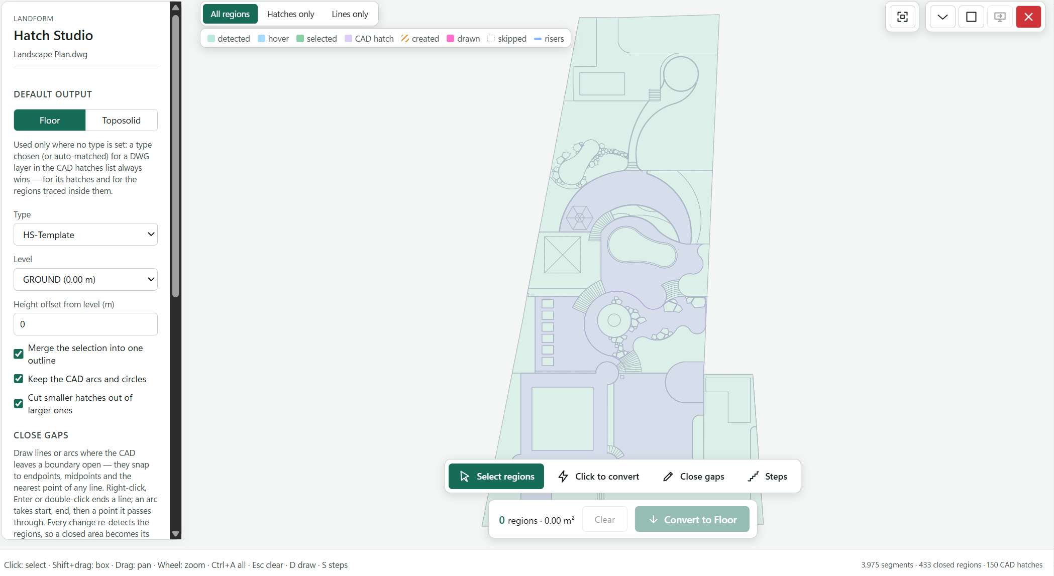
The drawing's linework with every detected closed region tinted. Drag to pan, scroll to zoom.
Explains the colours: detected, hover, selected, CAD hatch, created, drawn and skipped.
Keeps DWG hatch boundaries from mixing with the regions traced from linework.
Segments, closed regions and CAD hatches read from the drawing; progress and the convert summary also appear in the footer.
The default output, used wherever a CAD hatch layer has no type of its own.
The surface type, the level it sits on and its offset above that level.
Unions the selected regions with islands kept as openings, keeps true arcs, and stops overlapping fills from stacking.
Click a region to select it, or Shift+drag a box for many.
Each region you click is created at once with the current settings (Q).
Draw lines or arcs where a CAD boundary fails to meet; the regions are detected again straight away (D).
Drag across a run of regions to turn them into stacked floors or a Revit stair (S).
How many regions are selected and their area; Clear drops the selection.
Creates every selected region in one undoable step (or press Enter).
The mouse and keyboard shortcuts for the canvas.
Open LandForm tab → CAD panel → Hatch ▾ → Line Tracer.
Pick the drawing and choose what to read. Click the CAD import or link when asked. The Read CAD dialog then lists every layer and block with its object counts, heaviest first: untick layers you do not need, untick Read inside block references to skip plant and furniture symbols, or keep Read hatch objects as boundaries so the DWG's fills arrive as ready-made regions. Press Read CAD; your choice is remembered for the next time.
Read the canvas. The drawing opens in Hatch Studio with every closed region tinted and the footer counting segments, closed regions and CAD hatches. Drag to pan, scroll to zoom, and press Fit view to see it all. The legend explains the colours: detected, hover, selected, CAD hatch, created, drawn and skipped.
Set the default output. In the sidebar choose Floor or Toposolid, the Type, the Level and the Height offset from level (m). Tick Merge the selection into one outline to union the selected regions, with islands kept as openings; keep Keep the CAD arcs and circles on for true arcs; and leave Cut smaller hatches out of larger ones on so overlapping fills do not stack.
Give hatch layers their own types. Open the CAD hatches card. Each DWG layer row shows its hatch count and a type box: Auto-match picks the floor or toposolid type with the most similar name (LAWN to grass, POOL to water), Default uses the sidebar output, Skip (don't convert) leaves the layer out, or choose any Floor or Toposolid type. Press Select to add a layer's hatches to the selection or Convert to create them straight away. Expand widens the card so long names read in full.
Select regions. In Select regions mode click a region to select it, Shift+drag a box for many, and use All or Invert in the sidebar. Hide regions smaller than (m²) filters out slivers. Switch to Click to convert (Q) and each region you click is created at once with the current settings.
Close gaps where the CAD is open. Choose Close gaps (D), then Line (L) or Arc (A), and draw where a boundary fails to meet; points snap to endpoints, midpoints and the nearest point of any line. Right-click, Enter or a double-click ends a line, an arc takes start, end and a point it passes through, and Edit points (E) drags or deletes what you drew. Every change re-detects the regions, so a closed area becomes selectable immediately.
Build steps (optional). Choose Steps (S) and drag a line from the lower terrace across the treads onto the upper terrace, or click the bottom tread and then the top one. The card reports treads, risers, rise, the going range and the 2R+G comfort check. Give a Riser (mm) or a total Rise (m), keep Bottom and top from the model to read the surfaces at both ends, and set Build as to Stacked floors (one surface per tread at its own height) or Revit stair in the stair type you choose.
Convert. The action bar shows how many regions are selected and their area; press Convert (or Enter). The footer tracks the progress and finishes with "Created 3 floors and 2 toposolids on L1", listing anything Revit skipped. Press Clear or Esc to drop the selection.
Every selected region is now a Floor or Toposolid of its type on the chosen level, created in one undoable step named "LF-Line Tracer: Create Floors / Toposolids"; a stair built in Steps mode is one native Revit stair created as "LF-Line Tracer: Create Stair". Stacked step surfaces are numbered bottom to top in their Comments as "LandForm Steps - Tread N of M". Each surface remembers which regions it came from, so the canvas marks them created with the hatched colour, and a later Re-read CAD keeps that mark even after openings were cut or regions merged.
No separate LandForm window. This command runs directly from Revit selection and prompts; follow the workflow above and the messages shown beside the cursor or on Revit's status bar.
LandForm ribbon panel
Move structured data between Excel workbooks and Revit.
Excel · Excel · Surface Types
When a hardscape or soft-landscape schedule already lives in Excel, Surface Types saves you from building every paving, gravel or planting-bed type by hand. You pick the workbook and worksheet, choose a template type to copy, select the rows you want, and press Run. LandForm duplicates the template once per row, names the new type from the row's code and name, gives it a new material coloured from the row's picture or a palette, and writes every column of the row into matching type parameters so you can tag and schedule the types straight away.
LandForm tab→Excel panel→Excel ▾→Surface Types
Button tooltip: “Create floor or toposolid types from a workbook or table.”Surface Types walkthrough. Until it is published, the steps and the annotated window below walk through the same workflow.
Numbers on the screenshot match the legend. Hover a number or a legend row to highlight the other.
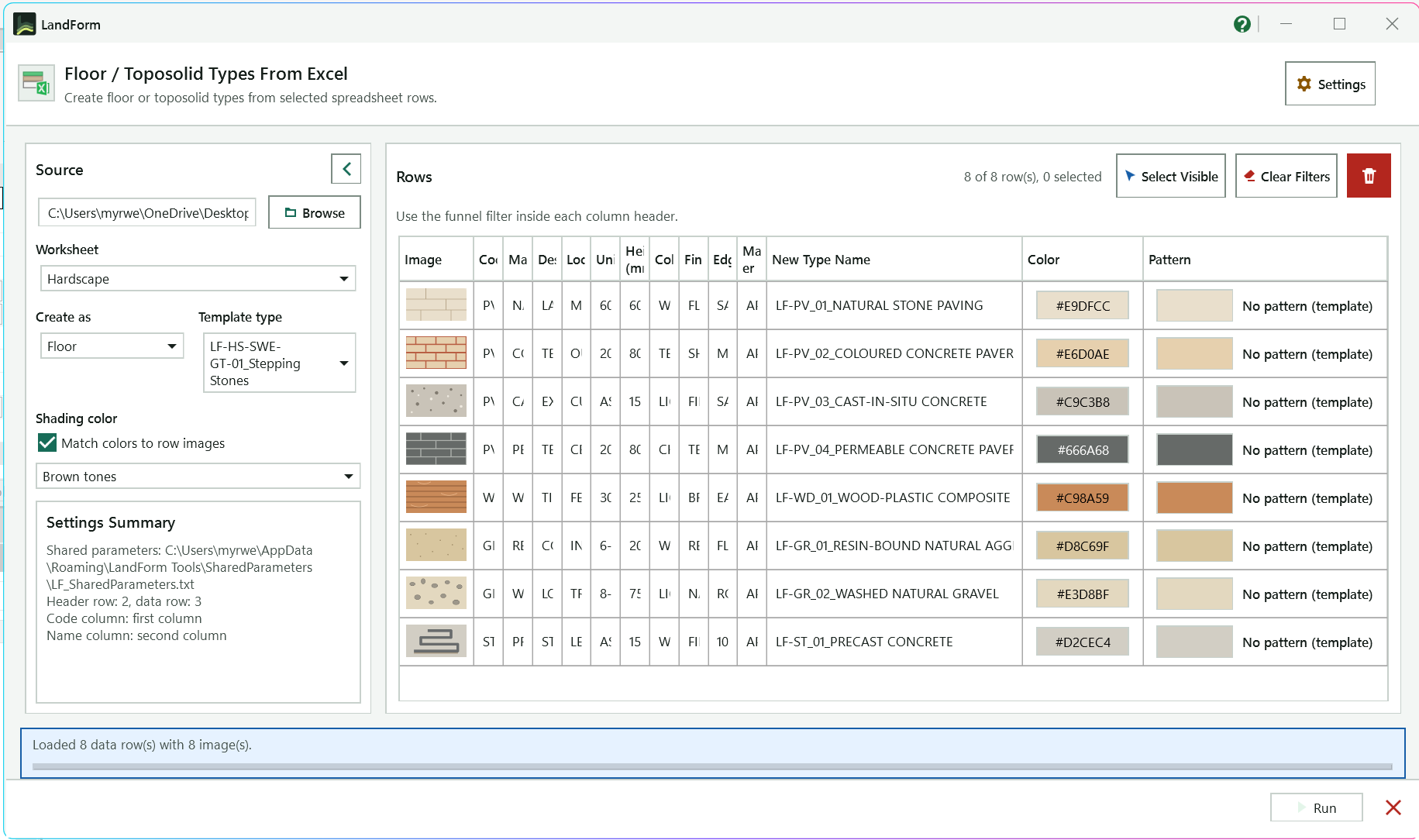
Opens the settings: heading and data rows, Code and Name columns, shared parameter file, prefix and naming rule.
Picks the Excel workbook; its path shows in the box beside the button.
The sheet whose rows are read into the table on the right.
Creates Floor types or Toposolid types.
The existing type duplicated once per selected row; its structure and layer 1 material are copied.
Match colors to row images takes each row's shading colour from its picture; the palette below colours rows without one.
Shows the shared parameter file, heading and data rows, and the Code and Name columns in use.
One line per spreadsheet row with its picture, sheet columns and proposed New Type Name. Filter with the funnel in a heading; edit a name cell to override the rule.
The row's shading colour; click a cell to choose a colour by hand.
The surface pattern for the row's material; click a cell to pick a pattern, No Pattern or Template Pattern.
Selects every row the filters leave visible; Clear Filters removes all column filters. The count shows visible and selected rows.
Reports what was loaded, or which layout setting to check when the sheet does not read correctly.
Creates one type per selected row and reports how many were created and skipped.
Hides the Source panel so the row table fills the window.
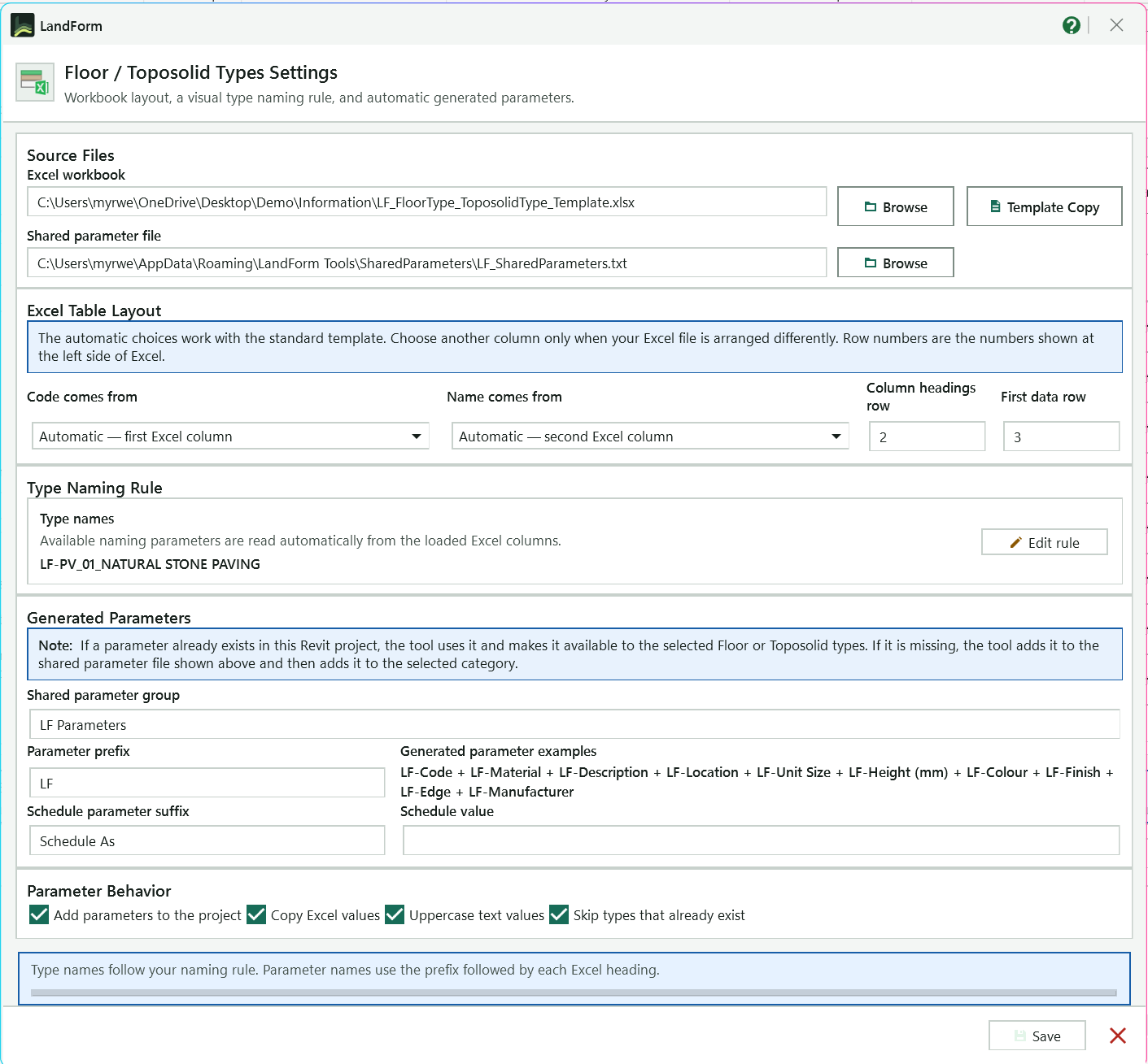
Default workbook opened with the tool; Browse picks a different file.
Saves an editable copy of the built-in template, already laid out the way the tool expects, and opens it.
The .txt file new type parameters are added to; Browse picks another.
The Excel columns used for the Code and Name parts of the default type name.
The Excel row holding the headings, and the First data row of values (2 and 3 in the template).
Opens the naming rule editor to build type names from columns, separators, prefixes and suffixes; the line beside it previews the first name.
Group inside the shared parameter file that holds the generated parameters.
Starts every generated parameter name, followed by a hyphen and the Excel heading.
Previews the parameter names the current prefix and headings produce.
Creates an extra schedule parameter filled with the Schedule value; leave the value blank to skip it.
Adds the parameters to the project, copies row values into them and writes text in capitals. Existing type names are always skipped, ticked or not.
Reminds you how type names and parameter names are built.
Saves the settings and closes the window.
Open LandForm tab → Excel panel → Excel ▾ → Surface Types.
Check the settings once. Press the settings button in the header. Confirm the Column headings row and First data row (2 and 3 in the template), which columns the Code and Name come from, the shared parameter file, and the parameter prefix (LF by default). Press Edit rule to change how type names are built, then Save.
Open the workbook. Click Browse and pick the Excel file, then choose the Worksheet. The rows appear on the right with a proposed New Type Name, an Image, a Color and a Pattern for each.
If the sheet does not read correctly, the status line explains which layout setting to check.
Choose what to create. Set Create as to Floor or Toposolid and pick the Template type to duplicate.
Set the colours. Tick Match colors to row images to take each row's shading colour from its picture, and pick a palette for rows without a picture. Click any Color cell to choose a colour by hand; hand-picked colours are kept when you change the palette.
Set the patterns (optional). Click a Pattern cell to choose a model or drafting pattern for that row's material, No Pattern, or Template Pattern to keep the template's pattern.
Select the rows. Use the funnel in a column heading to filter, then press Select Visible, or Ctrl- and Shift-click rows. Rows hidden by a filter are never created. Edit a New Type Name cell if one name needs to differ from the rule.
Run. Press Run. LandForm checks the inputs, creates the types and reports how many were created, how many existing names were skipped, and how many parameters were written.
The project now has one new Floor or Toposolid type per selected row, named from the naming rule or your edited name. Each type has its own copy of the template's layer 1 material with the same name as the type, Graphics > Shading set to the row's colour and the chosen surface pattern. Every spreadsheet column is written as a text type parameter named with the prefix and the heading, for example LF-Description, a LF-Schedule As parameter carries the schedule value if you set one, and rows with a picture get it as the type image. The whole run is one undo step named "LF-Surface Types: Create Types from Excel".
Hides the Source panel so the row table fills the window.
Excel workbook that contains floor or toposolid type data. The file path is saved in settings.
Select an Excel workbook.
Worksheet whose header row and data rows define type names and parameter values.
Choose whether selected Excel rows create Revit floor types or toposolid types.
Existing type duplicated for each selected spreadsheet row.
Fill the Color column with the base color of each row's image. The Color column becomes Graphics > Shading > Color of each new type's material. Only new types receive colors; an existing type name is reused without changing its material.
Colour palette used for rows without an image, or for every row when image matching is off. Click a Color cell to pick any colour.
Shows the Source panel again after it was collapsed.
Select only the rows currently visible after filtering.
Clear all column filters.
Select spreadsheet rows to convert into Revit types. Hidden filtered rows are ignored during creation.
Create floor or toposolid types from the selected rows.
Default workbook path used when the tool opens.
Choose the default workbook, or the shared parameter file on the line below.
Save an editable copy of the built-in Floor / Toposolid Types Excel template and open it.
Shared-parameter .txt file used for type parameter definitions.
Excel column used for the Code part of the default type name.
Excel column used for the Name part of the default type name.
Excel row containing headings such as Code, Material, and Description.
First Excel row containing values that will create types.
Opens the naming rule editor, where you assemble type names from Excel columns, separators, prefixes and suffixes with a live preview.
Group inside the shared-parameter file.
All generated parameter names use this prefix followed by a hyphen and the Excel header.
Optional suffix that creates a generated schedule/classification parameter.
Value written to the schedule/classification parameter. Leave blank to skip.
Make the generated parameters available to the selected Floor or Toposolid types.
Write each selected row value into matching generated type parameters.
Convert text values to uppercase before writing parameters.
Saved with the settings. Types whose name already exists are always skipped and never overwritten, whether or not this is ticked.
Save settings and close this dialog.

Excel · Excel · Family Placeholder
Early in a design you often know which benches, bins, lights, signs or trees you need long before the real manufacturer families exist. Family Placeholder lets you keep that list in Excel and still work with it in Revit: each selected row becomes a family in the category you choose, named from the row's code and name, carrying the row's values as parameters and its picture as the type image. You can schedule, tag and later swap these placeholders for real content. The tool creates and loads the families; it does not place any instances in the model.
LandForm tab→Excel panel→Excel ▾→Family Placeholder
Button tooltip: “Place family instances from workbook coordinates.”LF-Code.Family Placeholder walkthrough. Until it is published, the steps and the annotated window below walk through the same workflow.
Numbers on the screenshot match the legend. Hover a number or a legend row to highlight the other.
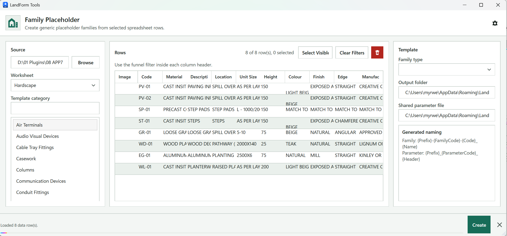
Opens the settings: heading and data rows, Code and Name columns, output folder, shared parameter file and parameter prefix.
Picks the Excel workbook; its path shows in the box beside the button.
Chooses the sheet whose rows become families.
Type here to search the category list below.
Adds the other mapped loadable categories to the landscape ones listed first.
Pick the category the new families are created in; each starts from that category's Revit template.
Reports what was loaded, here 6 rows with 6 pictures, and names the template of the chosen category.
One line per spreadsheet row with its picture and values. Filter with the funnel in a column heading and Ctrl- or Shift-click to select; filtered-out rows are never created.
Selects every row the filters leave visible.
Removes all column filters.
Clears the current row selection.
The name proposed by the naming rule; edit a cell when one family needs a different name.
Opens the validation checks, then creates and loads one family per selected row.
Collapses the Source panel so the row table fills the window.
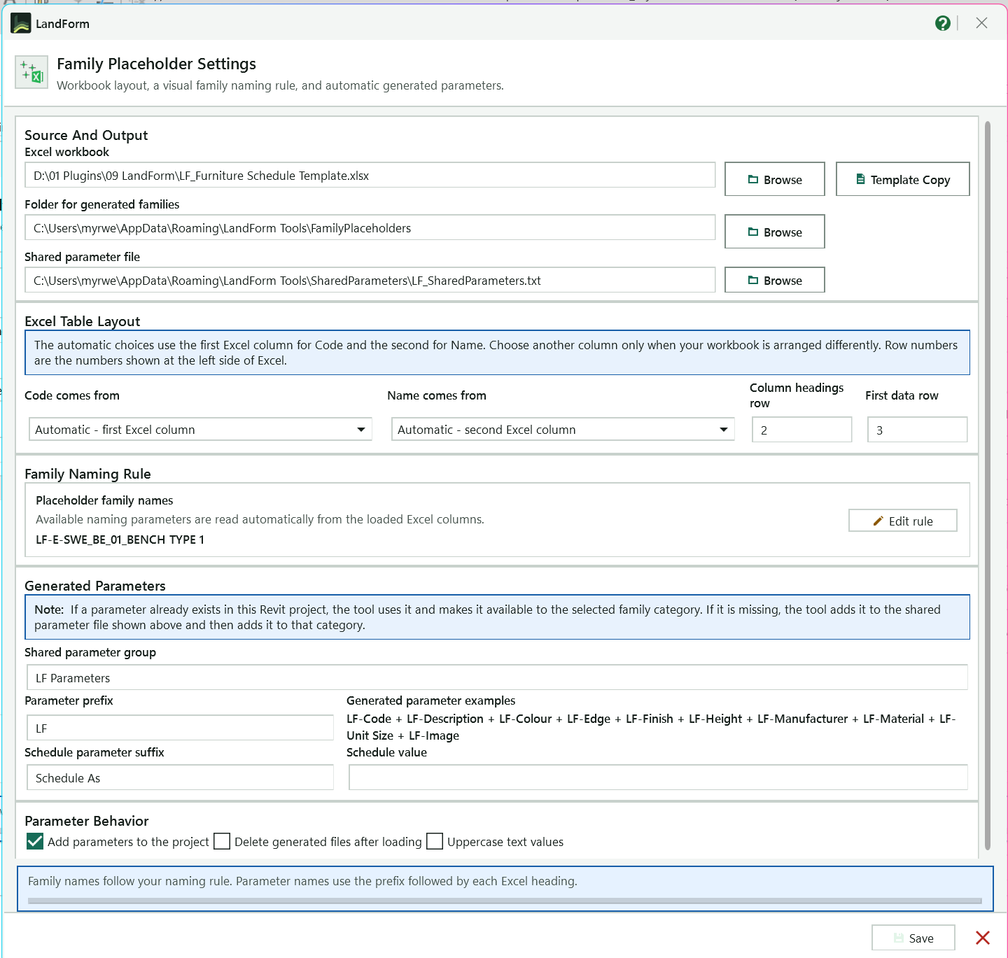
Default workbook opened with the tool; Browse picks another.
Saves an editable copy of the built-in Excel template and opens it.
Where the generated .rfa files are saved.
Shared-parameter .txt file used for the family parameters.
Excel columns used for the Code and Name parts of the default family name; Automatic takes the first and second columns.
Excel row numbers of the headings and of the first item, 2 and 3 in the template.
Sample family name built by the current naming rule.
Opens the naming rule editor to build names from columns, separators, prefixes and suffixes with a live preview.
Group inside the shared-parameter file that holds the parameters.
Text placed before every heading; the examples beside it show the resulting names, such as LF-Code.
Optional schedule parameter and the value written to it; leave the value blank to skip it.
Add parameters to the project binds them to the category, Delete generated files after loading clears every .rfa in the output folder, Uppercase text values writes text in capitals.
Reminds you how family and parameter names are formed.
Saves the settings and closes the window.
Open LandForm tab → Excel panel → Excel ▾ → Family Placeholder.
Check the settings once. Press the settings button in the header. Confirm the Column headings row and First data row (2 and 3 in the template), which columns the Code and Name come from, the Folder for generated families, the shared parameter file and the parameter prefix. Press Edit rule to change how family names are built, then Save.
Open the workbook. Click Browse, pick the Excel file and choose the Worksheet. The rows appear on the right with a proposed New Family Name and any row picture in the Image column.
Choose the family category. Pick a category in the Family category list. At first only landscape categories such as Planting, Site, Furniture, Entourage and Generic Models are listed; press Show all loadable for the other mapped categories, or type in the search box above the list. The status line names the Revit template that category uses.
Select the rows. Use the funnel in a column heading to filter, then press Select Visible, or Ctrl- and Shift-click rows. Rows hidden by a filter are never created. Edit a New Family Name cell if one name needs to differ from the rule.
Run and review the checks. Press Run. A validation window lists each check (document, workbook, worksheet, rows, category, family template, output folder, shared parameters, parameter naming) as OK, Note or Fix. Continue stays unavailable while any line says Fix; once all checks pass, press it to create the families.
Wait for the families to load. LandForm builds each family, saves it to the output folder, loads it into the project and reports how many families were created and how many parameters were written.
The project now contains one loaded family per selected row, in the chosen category, with a single type named like the family. Each family carries the row's values as type parameters named with the prefix and the heading, plus a schedule parameter if you set a schedule value, and rows with a picture get it as the type image. With Add parameters to the project on, the same parameters are bound to the category so they show in schedules and tags. Find the new families in the Project Browser under their category; the .rfa files stay in the output folder unless you chose to delete them.
Hides the Source panel so the row table fills the window.
Excel workbook containing the placeholder family data.
Select an Excel workbook.
Worksheet whose headers and data rows define the new families.
Search the displayed family categories.
Show every mapped loadable model category.
Landscape categories are shown by default. Use Show all loadable for other mapped model categories.
Shows the Source panel again after it was collapsed.
Select only the rows currently visible after filtering.
Clear all column filters.
Select spreadsheet rows to convert into placeholder families. Hidden filtered rows are ignored during creation.
Create placeholder families from the selected rows.
Default workbook path used when the tool opens.
Choose the default workbook, the output folder or the shared parameter file, depending on the line it sits on.
Save an editable copy of the built-in Family Placeholder Excel template and open it.
Folder where generated placeholder family files are saved.
Shared-parameter .txt file used for generated family parameters.
Excel column used for the Code part of the default family name.
Excel column used for the Name part of the default family name.
Excel row containing headings such as Code and Description.
First Excel row containing values that will create families.
Opens the naming rule editor, where you assemble family names from Excel columns, separators, prefixes and suffixes with a live preview.
Group inside the shared-parameter file.
Text placed before every Excel heading, for example LF-Code.
Optional heading used to create a schedule/classification parameter.
Value written to the schedule parameter. Leave blank to skip it.
Make generated parameters available to the selected family category in this project.
Delete generated .rfa files after the families are loaded into Revit. This clears every .rfa file in the output folder.
Convert Excel text values to uppercase before writing family parameters.
Save settings and close this dialog.
One line per check with its status (OK, Note or Fix) and the detail, such as the row count, the family template or the output folder.
Continue with family placeholder creation.

Excel · Excel · Schedule Link
Filling in plant codes, descriptions, suppliers or comments one element at a time in Revit is slow; in Excel it takes minutes. Schedule Link writes each schedule you tick to a workbook laid out like the Revit schedule, with every cell coloured to show whether it can be edited, and remembers which element each row belongs to. Edit the green and yellow cells, save the workbook, press Import, and LandForm writes only the values that changed back to the elements. You can also export a formatted copy just for review.
LandForm tab→Excel panel→Excel ▾→Schedule Link
Button tooltip: “Export schedules and import edited parameter values.”Schedule Link walkthrough. Until it is published, the steps and the annotated window below walk through the same workflow.
Numbers on the screenshot match the legend. Hover a number or a legend row to highlight the other.
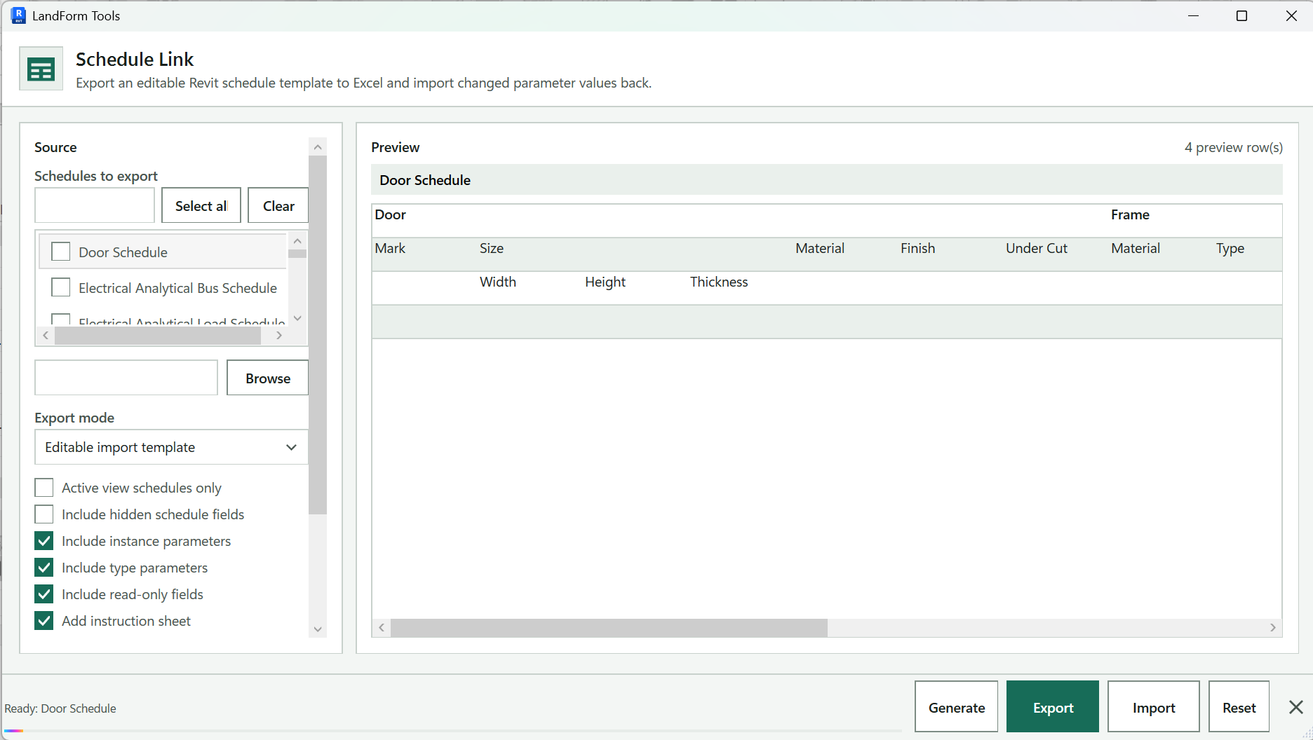
Filter the schedule list by name or category, then tick or untick every schedule the filter shows.
Tick the schedules to export or reset. Clicking a schedule also ticks it and shows it in the preview.
The .xlsx file used for both export and import. Browse chooses where to save it; by default it is named after the project.
Editable import template writes a workbook you can import back; Formatted schedule only writes a review copy that cannot be imported.
Lists only the schedules placed on the active sheet, or only the open schedule when a schedule is the active view.
Choose which values the workbook lets you edit (instance and type values) and whether read-only values are marked red. Include hidden schedule fields applies to Reset.
Adds an Instructions sheet to the workbook that explains the cell colours and the import rules.
The schedule shown in the preview and how many rows it has.
The schedule as it will appear in Excel, with its grouped headings, so you can check the layout before exporting.
The schedule that is ready, or the result of the last export, import or reset.
Reloads the schedule list and the preview after you change the model.
Writes the ticked schedules to the workbook and offers to open it in Excel.
Reads the edited workbook and writes changed values back to the elements. Not available in Formatted schedule only mode.
Clears the writable values shown in the ticked schedules after you confirm.
Open LandForm tab → Excel panel → Excel ▾ → Schedule Link.
Pick the schedules. Tick one or more schedules in Schedules to export. Use the search box and Select all for a long list, or tick Active view schedules only while a sheet is open to list just the schedules on that sheet.
Check the preview. The preview shows the selected schedule as it will appear in Excel. Press Generate if you changed the schedule in Revit after opening the tool.
Choose the mode and what can be edited. Keep Export mode on Editable import template for a round trip. Tick Include instance parameters and Include type parameters for the values you want to edit, and Include read-only fields to show read-only values in red rather than grey.
Export. Press Export, choose a file name if asked, and press Open Excel in the completion message. Each schedule gets its own sheet; a single schedule goes on a sheet called Schedule Data.
If type values were included, the message warns how many type cells the workbook contains.
Edit in Excel. Change values in the green (instance) and yellow (type) cells, then save the workbook. Do not rename or delete sheets, and do not insert or sort rows, because the hidden sheet maps each row to its element.
Import. Back in Revit, press Import. LandForm compares every editable cell with the model, writes only the changed values and reports how many cells were updated, skipped or failed and how many elements were missing.
The edited parameter values are now in the model, written in one undo step named "LF-Schedule Link: Import Excel", and the active view refreshes to show them. Cells whose value did not change, read-only cells and grey cells are left alone. Sheet Number changes are applied together so sheets can swap numbers, and duplicates are counted in the report. Reset clears writable values in the ticked schedules in one undo step named "LF-Schedule Link: Reset Values".
Search schedules by name or category.
Check every schedule currently visible in the filtered list.
Uncheck every schedule currently visible in the filtered list.
Tick a schedule to include it in Export and Reset.
Excel workbook used for export and import.
Choose where the exported .xlsx workbook is saved.
Editable import template for a round trip, or Formatted schedule only for a review copy that cannot be imported.
List only the schedules on the active sheet, or the active schedule itself.
Let Reset also clear values in fields that are hidden in the schedule. Exports always follow the visible columns.
Make instance values editable (green) in the export and importable.
Make type values editable (yellow) in the export and importable. A type value affects every element of that type.
Mark read-only values red in the export instead of grey. They are never imported.
Add an Instructions sheet that explains the colours and import rules.
Shows the selected schedule as it will be written to Excel, including its headings.
Refresh schedules and preview.
Write the ticked schedules to the workbook and offer to open it in Excel.
Write changed values from the edited workbook back to the matching elements.
Reset selected schedule values.

Excel · Excel · Import Table
Plant lists, material legends, area tables and specification notes are usually kept in Excel. Pasting them onto sheets as images goes stale, and retyping them takes hours. Import Table, whose window is called Import Excel, turns each worksheet into a key schedule whose header shows the table cell by cell, with your fonts, cell fills and embedded images. Each schedule remembers the file and worksheet it came from, so when the spreadsheet changes you open the tool, press Run, and the schedule is rebuilt in place on every sheet it is placed on.
LandForm tab→Excel panel→Excel ▾→Import Table
Button tooltip: “Import parameter values from a workbook or table.”Import Table walkthrough. Until it is published, the steps and the annotated window below walk through the same workflow.
Open LandForm tab → Excel panel → Excel ▾ → Import Table.
Add the tables. Press Add Tables and pick one or more files. Each worksheet or text file appears as a row under Tables with its source, type, worksheet, size, modified date and status, already ticked.
Schedules created earlier with this tool are listed automatically when the window opens; press Load Links to list them again.
Name the schedules. Edit the View Name of any row. New names start as "Table -" followed by the file and worksheet name.
Choose the category and region. Pick the Key schedule category. Set Region to Used Range, Print Area or Named Range; for a named range, type its name in the box below.
Set the look. Enter Text mm for the text height, Image mm for the largest side of embedded pictures, Row mm for the row height and Padding mm for the space inside each cell, then choose the Font. Tick Black and white to drop the Excel cell colours.
Pick the rows to process. Untick any row you do not want, or select rows and press the delete button to remove them from the list.
Run. Press Run. LandForm creates a key schedule for each new table, updates the schedules that are already linked, and writes the outcome into each row's Status. The status line sums up how many schedules were created, updated or skipped and how many cells and images were written.
Each ticked table now exists as a key schedule in the chosen category, named as you set it, with the spreadsheet drawn in its header: the text in your font and size, cell background and text colours unless you chose black and white, and pictures embedded in their cells. Place it on a sheet like any other schedule. A linked schedule keeps its link to the source file and worksheet, so running the tool again replaces its content with the current spreadsheet. The whole run is one undo step named "LF-Import Table: Create Schedules".
Choose .xlsx, .xlsm, .csv, .tsv or .txt files. Each worksheet or text file is added as a table row.
List the key schedules in this model that were created by Import Table and are linked to a source file.
Category the new key schedules are created in.
Part of each worksheet to read: Used Range, Print Area or Named Range.
Named Excel range used when Region is Named Range.
Text height in millimetres, from 1 to 20.
Maximum width or height used for embedded Excel images.
Row height in millimetres, from 3 to 100.
Space inside each cell in millimetres, from 0 to 20.
Font used for imported schedule text.
Ignore Excel cell fills and text colours and create the schedule in black and white.
The tables to process, with source file, type, worksheet, editable view name, size, modified date and status. Untick a row to leave it out.
Create or update the table views.